Boiler waste heat recovery system

A recovery system, boiler waste heat technology, applied in steam boilers, steam boiler accessories, steam boiler components, etc., can solve the problem of high boiler flue gas outlet temperature, achieve high waste heat recovery rate, avoid blockage, and reliable structure

Active Publication Date: 2014-10-15
山西臣功新能源科技有限公司
View PDF6 Cites 4 Cited by
  • Summary
  • Abstract
  • Description
  • Claims
  • Application Information

AI Technical Summary

Problems solved by technology

It has been verified that the boiler flue gas outlet temperature is as high as 260°C-320°C; the actual application

Method used


Image

  • Boiler waste heat recovery system
  • Boiler waste heat recovery system

Examples


Embodiment 1

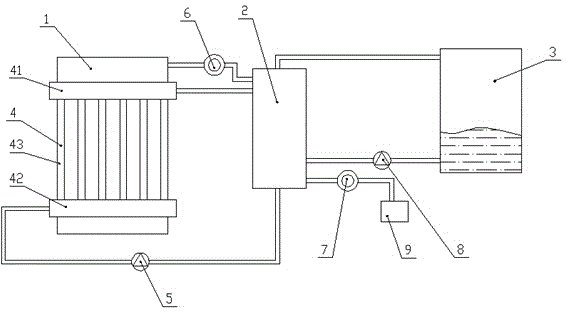
[0024] This embodiment provides a boiler waste heat recovery system, such as figure 1 As shown, the boiler waste heat recovery system includes a boiler 1 , waste heat recovery equipment, a heat exchanger 2 and a steam tank 3 . The waste heat recovery equipment transfers the waste heat of the boiler to the steam tank 3 through the heat exchanger 2, heats the cold water in the steam tank 3 and converts it into steam and stores it in the steam tank 3.

[0025] The waste heat recovery equipment includes a heat exchange tube assembly 4 arranged on the outer periphery of the boiler 1 , and the heat exchange tube assembly 4 , the first circulating pump 5 and the heat exchanger 2 form a refrigerant circulation loop. The heat exchange tube assembly 4 includes a first annular pipe 41 surrounding the upper part of the boiler 1, a second annular pipe 42 surrounding the lower part of the boiler 1, and a plurality of straight pipes 43 connecting the first annular pipe 41 and the second annu...

Embodiment 2

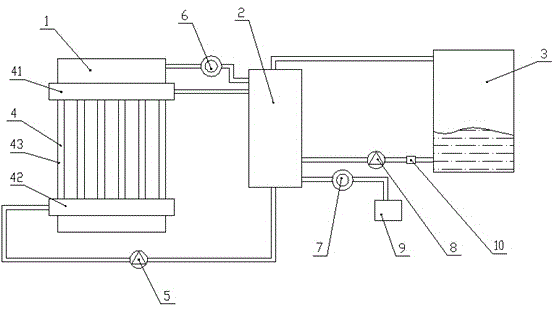
[0035] This embodiment provides a boiler waste heat recovery system, such as figure 2 As shown, the boiler waste heat recovery system includes a boiler 1 , waste heat recovery equipment, a heat exchanger 2 and a steam tank 3 . The waste heat recovery equipment transfers the waste heat of the boiler to the steam tank 3 through the heat exchanger 2, heats the cold water in the steam tank 3 and converts it into steam and stores it in the steam tank 3.

[0036] The difference is that, in this embodiment, a filter device 10 is provided on the outlet pipeline of the cold water outlet of the steam tank 3 . By setting the filter device 10, the water in the pipeline can be filtered to further avoid the blockage of the pipeline and ensure the reliability of use.


PUM


Abstract

The invention discloses a boiler waste heat recovery system and relates to the field of the heat power supply environmental protection technology. By the boiler waste heat recovery system, heat radiated from the periphery of the boiler and flue-gas waste heat exhausted from the boiler are simultaneously collected, and the waste heat of the boiler is fully absorbed with high waste heat recycling efficiency; since a heat exchange tube component is arranged on the periphery of the boiler rather than the inner portion of the boiler, the heat in the boiler is not absorbed, causing no affection to the boiler; a waste gas outlet is connected with a heat exchanger through a first induced draft fan, and a gas outlet of the heat exchanger is connected with a waste gas treatment device through a second induced draft fan, thus smoke in the waste gas is prevented from accumulating in a pipeline to cause blocking, and structure is reliable.

Description

technical field [0001] The invention relates to the technical field of heat supply and environmental protection, in particular to a boiler waste heat recovery system. Background technique [0002] During the operation of industrial boilers, there are problems such as high exhaust gas temperature, insufficient combustion, and low boiler thermal efficiency. The total amount of energy in the exhaust heat loss is huge. Making full use of this part of energy to heat the air and water, increasing the air temperature and feed water temperature can improve the fuel utilization efficiency to a certain extent. my country's industrial boilers have been using cast iron economizers to recover flue gas waste heat for nearly 50 years. The heat transfer efficiency is low, the dust accumulation is difficult to clean, and it is not resistant to corrosion. Several types of devices have also been developed for the recovery and utilization of waste heat from industrial boilers at home and abroa...

Claims


Application Information

Patent Timeline
IPC IPC(8): F22B37/00F24H9/00
Inventor 王琬
Owner 山西臣功新能源科技有限公司
Why Eureka
Try Eureka