Speed regulation method based on combined circulation gas turbine system model

A combined cycle and system model technology, applied in special data processing applications, instruments, electrical digital data processing, etc., can solve the problems of not clearly defining the general model of the gas turbine speed control system, not given, etc., to achieve a wide range of applications, Fast response and reduced steady-state error

Active Publication Date: 2014-10-15
SHANGHAI MUNICIPAL ELECTRIC POWER CO +1
View PDF2 Cites 22 Cited by
  • Summary
  • Abstract
  • Description
  • Claims
  • Application Information

AI Technical Summary

Problems solved by technology

The State Grid Enterprise Standard "Guidelines for Measuring and Modeling Parameters of Synchronous Generator Prime Motive and Its Regulation System" issued in 2012 did not provide a complete standard mathematical model that can characterize the domestic F-class combined cycle gas turbine speed regulation system. What is provided is the general model of some units and some parameter tables of the speed control system, so the modeling work of the speed control system of the F-class combined cycle gas turbine cannot be effectively completed according to the guidelines
The general model of each unit of the gas turbine speed control system is not clearly defined in the domestic power system analysis comprehensive program PSD-BPA dynamic simulation program

Method used


Image

  • Speed regulation method based on combined circulation gas turbine system model
  • Speed regulation method based on combined circulation gas turbine system model
  • Speed regulation method based on combined circulation gas turbine system model

Examples


Embodiment

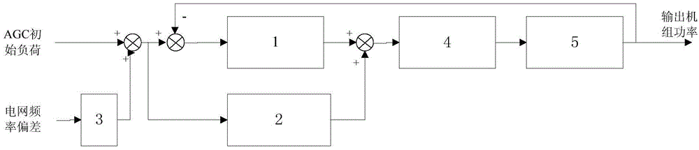
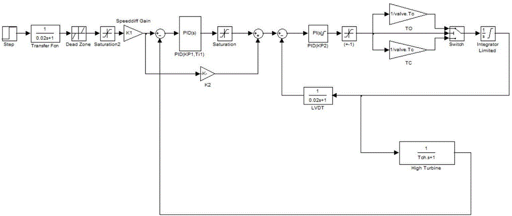
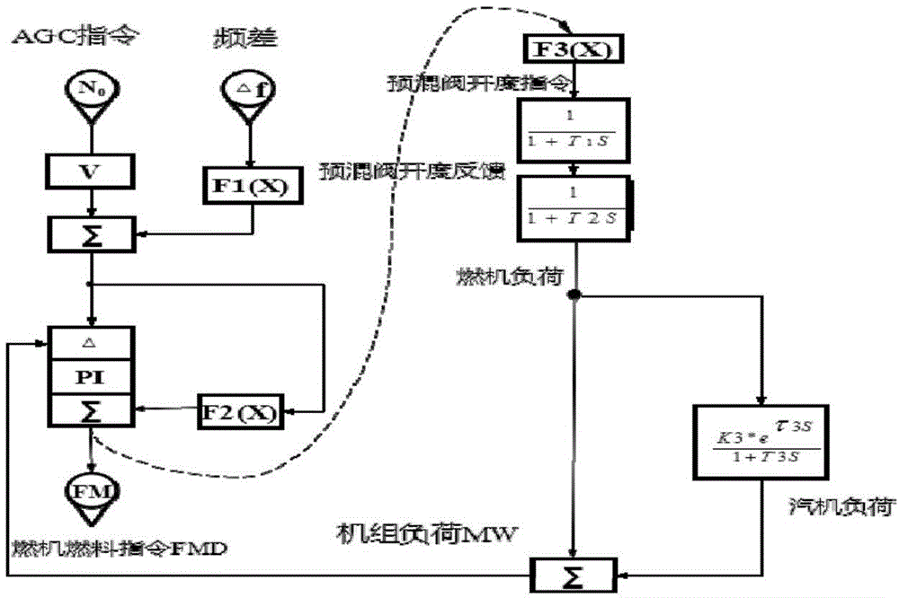
[0029] Such as figure 1 As shown, the present invention provides a control model of an F-class gas turbine speed regulation system, the model mainly includes three model units, a regulation system model unit, an electro-hydraulic servo system model unit, a prime mover model unit, and its frequency control principle diagram Such as image 3 As shown, the same feed-forward and feedback non-difference PID control as the actual load control of the unit is adopted in the regulation system model unit: firstly, the power change demand value of the primary frequency regulation generated by the grid frequency deviation is added to the AGC initial load to obtain the combined cycle combustion The actual load command of the combined cycle gas turbine is then passed to the model unit of the fuel valve electro-hydraulic servo system through the fuel valve command generated by the actual load command of the combined cycle gas turbine through feed-forward and feedback non-difference PID contr...


PUM


Abstract

The invention relates to a speed regulation method based on a combined circulation gas turbine system model. The speed regulation method is characterized by comprising the following steps: 1) establishing a combined circulation gas turbine system model which comprises a regulation system model unit, a fuel valve electro hydraulic servo system model unit and a combined circulation gas turbine prime mover model unit, wherein the regulation system model unit, the fuel valve electro hydraulic servo system model unit and the combined circulation gas turbine prime mover model unit are connected in sequence; 2) adopting feedforward and feedback indifference PID (Proportion Integration Differentiation) control in the regulation system model unit, adding a one-time frequency modulation power change requirement value generated by power grid frequency deviation with AGC ((Automatic Generation Control) initial load to obtain a practical load command of the combined circulation gas turbine, and carrying out the feedforward and feedback indifference PID control to the practical load command to generate a fuel value command; 3) according to the fuel valve command, generating a fuel amount signal in the combined circulation gas turbine prime mover model unit; and 4) according to the fuel amount signal, controlling the combined circulation gas turbine in the combined circulation gas turbine prime mover model unit, and regulating the output power of the combined circulation gas turbine. The invention has the advantages of being high in control precision and high in response speed.

Description

technical field [0001] The invention relates to a speed regulation method, in particular to a speed regulation method based on a combined cycle gas turbine system model. Background technique [0002] The East China Power Grid has entered a new pattern of multi-point DC and UHV AC-DC interconnection. The characteristics of the receiving-end power grid are obvious, and the frequency stability of the power grid is becoming more and more prominent. Generator set prime mover and its speed control system are important network-related equipment, which have a significant impact on the frequency stability of the power system grid. [0003] In recent years, with the continuous increase in the number of gas turbines, their weight in the installed capacity of the entire grid can no longer be ignored. The refined operation and management of the power grid has put forward an urgent demand for speed regulation system modeling. The State Grid Enterprise Standard "Guidelines for Measuring a...

Claims


Application Information

Patent Timeline
Patent Type & Authority Applications(China)
IPC IPC(8): G06F17/50G06Q50/06
CPCG06F30/00
Inventor 单英雷李福兴
Owner SHANGHAI MUNICIPAL ELECTRIC POWER CO
Why Eureka
Try Eureka