Smoke conveying device and method for injecting oxygen-enriched gas into flue
An oxygen-enriched gas and delivery device technology, which is applied in the direction of non-flammable liquid/gas delivery, combustion methods, indirect carbon dioxide emission reduction, etc., can solve the problem of unsafe and unstable dynamic pressure system, oxygen-enriched gas and flue gas in the flue Mix unevenly and other problems, to achieve the effect of stable mixing uniformity and enhanced mixing intensity
- Summary
- Abstract
- Description
- Claims
- Application Information
AI Technical Summary
Problems solved by technology
Method used
Image
Examples
Embodiment 1
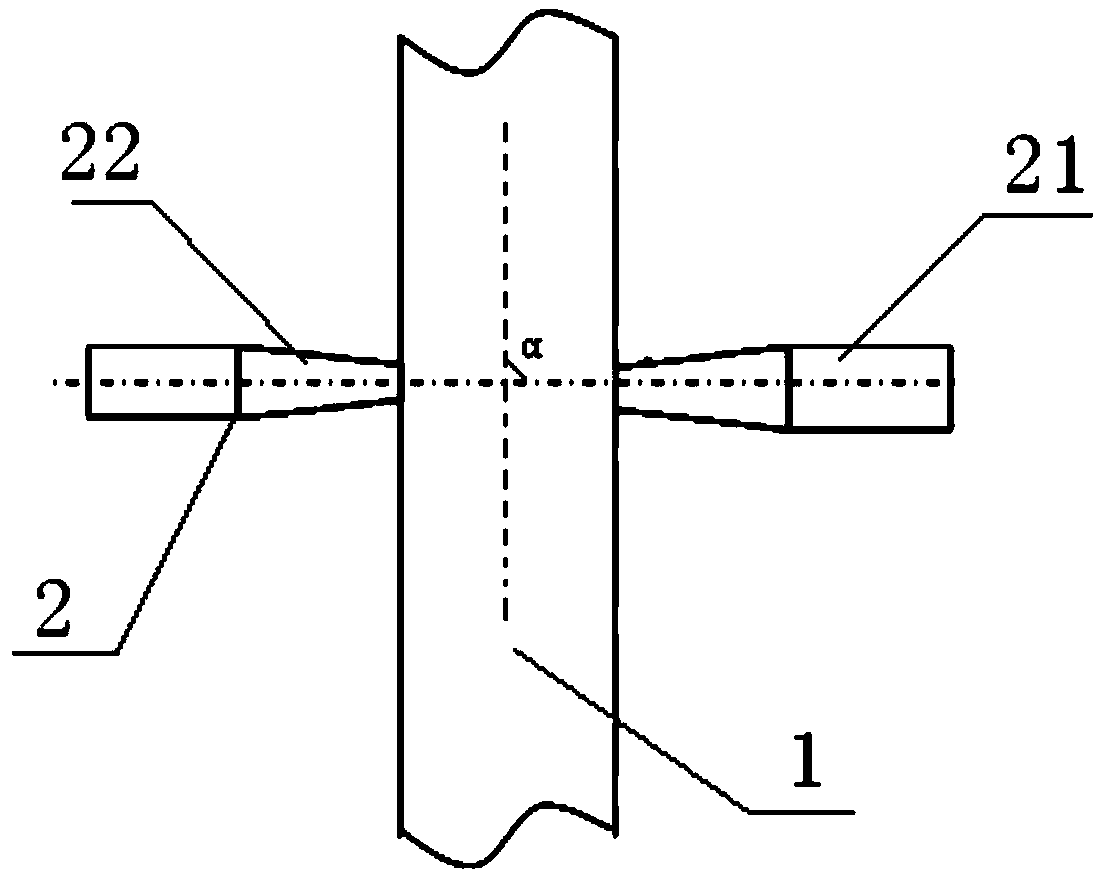
[0033] Such as figure 1 As shown, the flue gas conveying device is symmetrically provided with two oxygen injectors 2 on the side of the cylindrical flue 1, and the oxygen injector 2 includes a straight cylinder part 21 and a tapered part 22, and the tapered part 22 One end is connected to the flue 1 through a flange, and the other end is connected to the straight part 21 through welding, and the flow direction of the flue gas delivered through the flue 1 and the flow direction of the oxygen-enriched gas injected by the oxygen injector 2 are connected. The included angle α is equal to 90°, wherein the tapered portion 22 is a straight-flow circular tube, and the diameter ratio of the two ends of the tapered portion 22 is 2:1.
[0034] The oxygen-enriched gas with an oxygen content of 97% is injected into the flue at a flow rate of 35m / s through the above-mentioned device, and quickly mixed with the flue gas with a flow rate of 15m / s, and then sent into the boiler to participate...
Embodiment 2
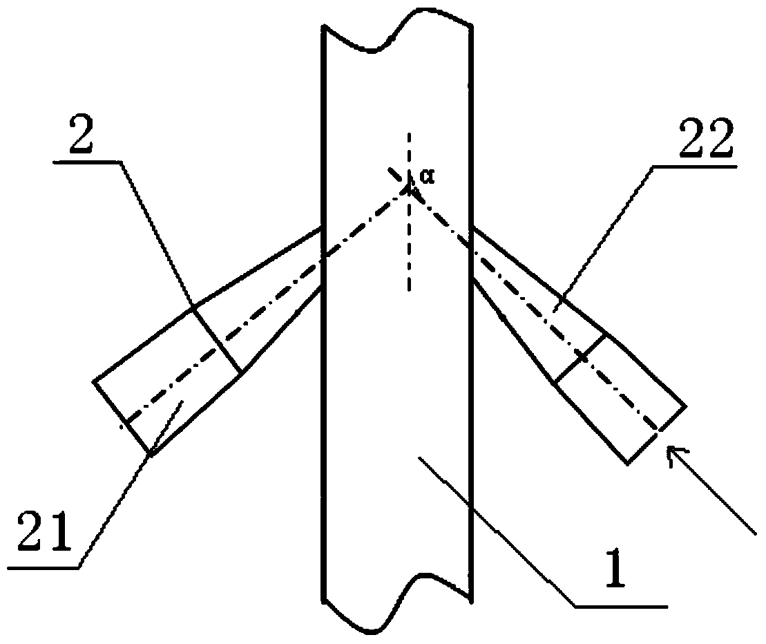
[0036] Such as figure 2 As shown, the flue gas conveying device is symmetrically provided with two oxygen injectors 2 on the side of the cylindrical flue 1, and the oxygen injector 2 includes a straight cylinder part 21 and a tapered part 22, and the tapered part 22 One end is connected to the flue 1 through a flange, and the other end is connected to the straight part 21 through welding, and the flow direction of the flue gas delivered through the flue 1 and the flow direction of the oxygen-enriched gas injected by the oxygen injector 2 are connected. The included angle α is equal to 120°, wherein the tapered part 22 is a swirl tube, and the diameter ratio of the two ends of the tapered part 22 is 1.5:1.
[0037] The oxygen-enriched gas with an oxygen content of 96% is injected into the flue at a flow rate of 25m / s through the above-mentioned device, and quickly mixed evenly with the flue gas with a flow rate of 13m / s, and then sent into the boiler to participate in combusti...
Embodiment 3
[0039]The flue gas conveying device is that four oxygen injectors 2 are arranged symmetrically on the side of the rectangular flue 1, and the oxygen injectors 2 include a straight part 21 and a tapered part 22, and one end of the tapered part 22 is connected to the flue gas. The channel 1 is connected by a flange, and the other end is connected to the straight part 21 by welding, and the angle α between the flow direction of the flue gas delivered through the flue 1 and the flow direction of the oxygen-enriched gas injected by the oxygen injector 2 is equal to 135°, wherein, the tapered part 22 is a straight-flow circular tube, and the diameter ratio of the two ends of the tapered part 22 is 1.2:1.
[0040] The oxygen-enriched gas with an oxygen content of 95% is injected into the flue at a flow rate of 5m / s through the above-mentioned device, and quickly mixed evenly with the flue gas with a flow rate of 10m / s, and then sent into the boiler to participate in combustion, accord...
PUM
 Abstract
Description
Claims
Application Information
 - R&D
- Intellectual Property
- Life Sciences
- Materials
- Tech Scout
- Unparalleled Data Quality
- Higher Quality Content
- 60% Fewer Hallucinations
Browse by: Latest US Patents, China's latest patents, Technical Efficacy Thesaurus, Application Domain, Technology Topic, Popular Technical Reports.
© 2025 PatSnap. All rights reserved.Legal|Privacy policy|Modern Slavery Act Transparency Statement|Sitemap|About US| Contact US: help@patsnap.com


