Light-emitting devices providing asymmetrical propagation of light

A technology of light-emitting devices and light-emitting elements, which is applied in the direction of lighting devices, components of lighting devices, semiconductor devices of light-emitting elements, etc., and can solve problems such as light energy loss and conversion properties

Active Publication Date: 2014-10-22
QUARKSTAR
View PDF6 Cites 7 Cited by
  • Summary
  • Abstract
  • Description
  • Claims
  • Application Information

AI Technical Summary

Problems solved by technology

[0006] Although new types of phosphors are being actively researched and developed, however, the construction of PLED-based light-emitting devices presents further challenges due to the nature of the available light-emitting materials.
These challenges include, for example, loss of light energy from photon conversion, self-heating of the phosphor from Stokes loss, dependence of photon conversion properties on operating temperature, chemical degradation of phosphor due to overheating or other damage Degradation due to permanent changes in physical composition, dependence of conversion properties on light intensity, propagation of light in undesired directions due to random emission of converted light emitted from phosphors, undesired chemical properties of phosphors and Controlled Deposition of Phosphors in Light-Emitting Devices

Method used


Image

  • Light-emitting devices providing asymmetrical propagation of light
  • Light-emitting devices providing asymmetrical propagation of light
  • Light-emitting devices providing asymmetrical propagation of light

Examples


Embodiment Construction

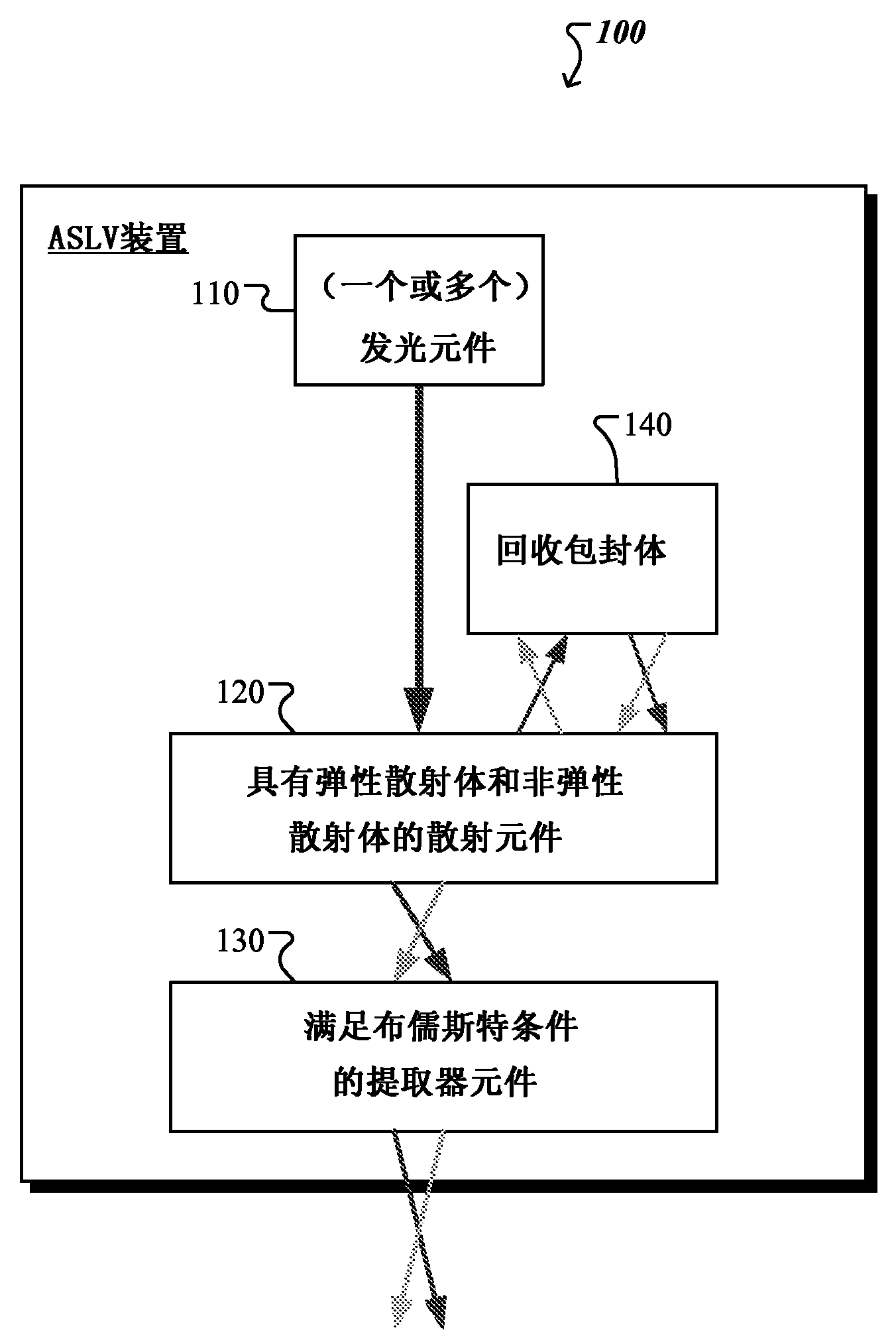
[0201] Figure 1A A schematic diagram showing an example of a light emitting device 100 comprising a light emitting element 110 (LEE), a scattering element 120 (also called first optical element), an extractor element 130 (also called second optical element) and recover the envelope 140 . The light emitting device 100 efficiently provides broadband homogeneous light to the surrounding environment across a wide range of angles.

[0202] Light emitting element 110 is configured to generate and emit light during operation. For example, the spectral power distribution of the light (also referred to as pump light) emitted by the light emitting element 110 can be blue. The spectral power distribution of visible light is known as chromaticity. For example, in general, light-emitting element 110 is one that emits in a region or combination of regions of the electromagnetic spectrum for the visible, infrared, and / or ultraviolet regions when energized by applying a potential differenc...


PUM


Abstract

A variety of light-emitting devices for general illumination utilizing solid state light sources (e.g., light emitting diodes) are disclosed. In general, the devices include a scattering element in combination with an extractor element. The scattering element, which may include elastic and / or inelastic scattering centers, is spaced apart from the light source element. Opposite sides of the scattering element have asymmetric optical interfaces, there being a larger refractive index mismatch at the interface facing the light emitting element than the interface between the scattering element and the extractor element. Such a structure favors forward scattering of light from the scattering element. In other words, the system favors scattering out of the scattering element into the extractor element over backscattering light towards the light source element. The extractor element, in turn, is sized and shaped to reduce reflection of light exiting the light-emitting device at the devices interface with the ambient environment.

Description

[0001] Cross References to Related Applications [0002] This application claims the benefit of the following provisional applications: Provisional Application No. 61 / 563,513l, filed November 23, 2011; Provisional Application No. 61 / 595,663, filed February 6, 2012; and Provisional Application No. 61 / 700,724, filed September 13, 2012. The entire contents of each of these priority applications are hereby incorporated by reference. technical field [0003] The present invention relates generally to light emitting devices, and in particular, to light emitting devices featuring solid state light emitting elements and scattering elements and extractor elements away from the light emitting elements. Background technique [0004] Light emitting elements are ubiquitous in the modern world, being used in applications ranging from general lighting (eg, light bulbs) to illuminated electronic information displays (eg, LCD backlights and front lights) to medical devices and treatments. ...

Claims


Application Information

Patent Timeline
Patent Type & Authority Applications(China)
IPC IPC(8): H01L33/00
CPCF21K9/50H01L2933/0091H01L33/58F21K9/60F21V5/008G02B19/0028G02B19/0066G02B5/0236G02B5/0278G02B19/0061F21V13/08F21V13/02
Inventor 罗兰德·H·海茨乔治·E·史密斯罗伯特·C·加德纳路易斯·勒曼
Owner QUARKSTAR
Why Eureka
Try Eureka