
A kind of solar heat collector with film hole structure

A technology of solar heat collectors and film holes, which is applied in the field of solar energy, can solve the problems of thermal conductivity of discontinuous phase change materials, failure to solve high-efficiency absorption of solar energy, and failure of heat collectors to work normally, so as to achieve continuous and stable supply , prevent heat loss, slow heat transfer effect

Active Publication Date: 2016-03-30
XI AN JIAOTONG UNIV
View PDF7 Cites 0 Cited by
  • Summary
  • Abstract
  • Description
  • Claims
  • Application Information

AI Technical Summary

Problems solved by technology

But the solar energy of this structure has the following disadvantages: water flows directly in the vacuum tube, once the vacuum glass tube is broken, the water will flow out from the vacuum glass tube, and a broken vacuum glass tube will cause the entire collector to fail to work normally
However, the inherent characteristics of the existing organic phase change materials are that the thermal conductivity is small and the heat transfer is too slow, resulting in poor energy storage effect and low energy storage efficiency.
Especially the discontinuity and discontinuity of solar radiation and the low thermal conductivity of phase change materials, the speed of phase change energy storage is very low
Patent 200810123873.6 discloses "a solar flat collector with high-porosity metal foam". An integrated structure of serpentine tubes, high-porosity metal foam and phase-change materials is arranged under the heat-absorbing plate to achieve efficient and rapid energy storage. But the patent fails to solve the problem of efficient absorption of solar energy

Method used


Image

  • A kind of solar heat collector with film hole structure
  • A kind of solar heat collector with film hole structure
  • A kind of solar heat collector with film hole structure

Examples


Embodiment Construction

[0019] The present invention will be described in detail below in conjunction with the accompanying drawings.

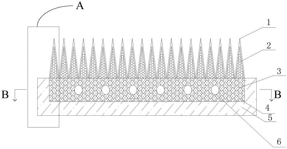
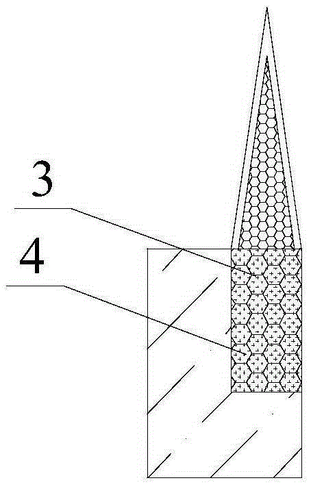
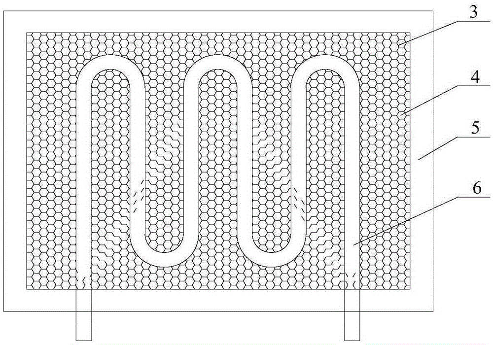
[0020] Such as figure 1 and figure 2 As shown, the present invention includes an incubator 5 with an open upper end, the incubator is made of insulating material, a phase change material layer 3 in contact with the inner wall of the incubator is provided in the incubator 5, and a snake is arranged inside the phase change material layer 3. shaped tube 6 and metal foam 4 with large pore diameter, the porosity of the metal foam 4 with large pore diameter is 0.3-0.9, and the pore diameter is 200-2000 μm. The top of the phase change material layer 3 is provided with a conical metal foam layer 2, and the outer wall of the conical metal foam layer 2 is wrapped with a transparent outer layer 1. The transparent outer layer 1 is wrapped on the conical metal foam layer 2 and can pass through sunlight. film of transparent material. Wherein, the metal foam layer 2 includes se...


PUM

PropertyMeasurementUnit
pore sizeaaaaaaaaaa
pore sizeaaaaaaaaaa
thicknessaaaaaaaaaa

Abstract

A solar heat collector with a film hole structure comprises a heat preservation box with the upper end open, a phase-change material layer is arranged in the heat preservation box, a coiled pipe is arranged in the phase-change material layer, a conical metal foam layer is arranged at the top of the phase-change material layer, the outer wall of the conical metal foam layer is wrapped by a transparent outer layer which can transmit light, and metal foam is added into the phase-change material layer. The content of air in a heat collecting area is greatly increased due to the metal foam structure, an air layer is divided into parts with small volumes, and therefore heat loss caused by convection is prevented. Sunlight can illuminate the conical metal foam layer through the transparent outer layer, the conical metal foam layer has the function of a heat absorber and converts light energy into heat energy, and the transparent outer layer has the function of a heat insulating layer and prevents heat in the heat absorber from being dissipated to the outside. The solar heat collector can effectively absorb solar radiation and fast store the energy and can be widely used for drying, food processing, household heat supplying , cooking and the like.

Description

technical field [0001] The invention belongs to the technical field of solar energy and relates to a heat collector device capable of storing energy, in particular to a solar heat collector with a membrane hole structure. Background technique [0002] At present, the utilization of solar energy mainly consists of thermal energy absorption and photoelectric conversion. Now the more mature thermal energy absorption technology is the glass vacuum tube collector, which converts the collected solar energy into heat energy through the vacuum glass tube to heat the water in the vacuum glass tube to Get the hot water you need. However, the solar energy of this structure has the following disadvantages: water flows directly in the vacuum tube, and once the vacuum glass tube is broken, the water will flow out from the vacuum glass tube, and a broken vacuum glass tube will cause the entire collector to fail to work normally. In addition, the vacuum glass tube itself is very brittle an...

Claims


Application Information

Patent Timeline
Patent Type & Authority Patents(China)
IPC IPC(8): F24J2/34F24J2/48F24J2/46
CPCY02E10/40
Inventor 屈治国周亮高怀斌
Owner XI AN JIAOTONG UNIV
Learn More