Micro-combustion thermal-photovoltaic generating device with regeneration function

A thermal photovoltaic power generation and micro-combustion technology, applied in photovoltaic power generation, photovoltaic power stations, burners, etc., can solve the problems of short continuous working time and low energy density, and achieve convenient refueling, high energy density and compact structure. Effect

Inactive Publication Date: 2014-11-05
TIANJIN UNIV
View PDF8 Cites 6 Cited by
  • Summary
  • Abstract
  • Description
  • Claims
  • Application Information

AI Technical Summary

Problems solved by technology

But in some occasions, due to the limitations of processing technology, fuel combustion cannot play its role, such as portable electronic devices such as mobile phones and laptop computers. At present, people mainly rely on batteries to provide energy for them.
Due to the ch

Method used


Image

  • Micro-combustion thermal-photovoltaic generating device with regeneration function
  • Micro-combustion thermal-photovoltaic generating device with regeneration function
  • Micro-combustion thermal-photovoltaic generating device with regeneration function

Examples


Embodiment 1

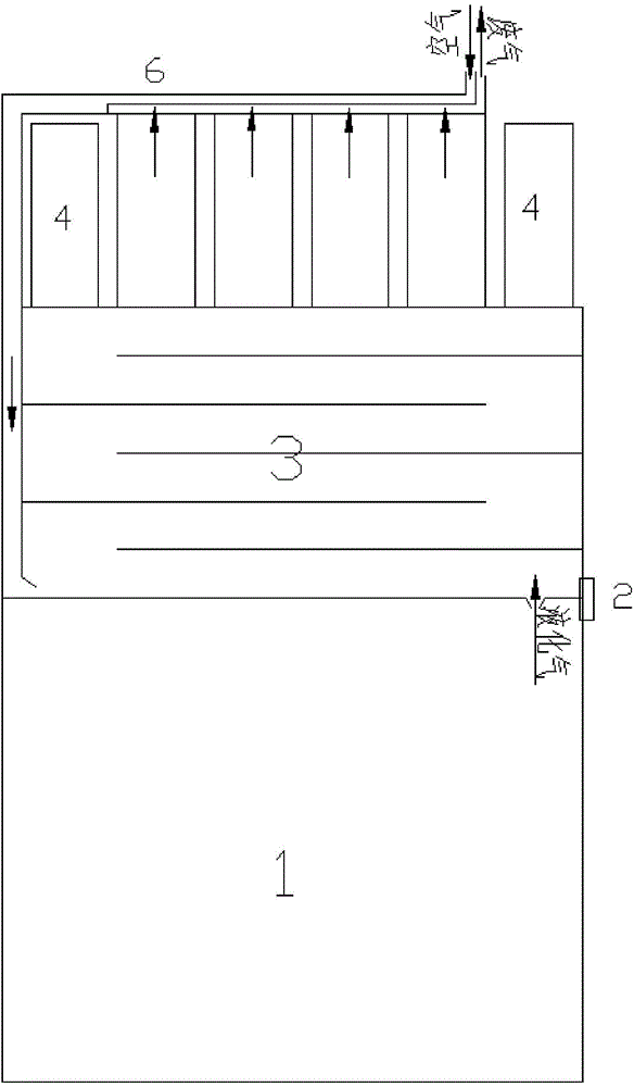
[0031] refer to figure 1 , image 3 , to illustrate the specific technical solutions of the present invention. A micro-combustion thermal photovoltaic power generation device with heat recovery function, comprising: a housing, and placed in the housing: a fuel tank 1 for storing fuel, and the fuel can be liquefied hydrogen, methane, n-butane or these substances The fuel flow regulating valve 2 controls the flow of fuel after gasification; the mixing chamber 3; the igniter 4 adopts piezoelectric material and uses piezoelectric effect to ignite; 12 micro burners 5 are arranged side by side;

[0032] The thermal photovoltaic panel 7 absorbs the thermal radiation energy on the wall of the micro burner and converts it into electrical energy, using gallium antimonide GaSb or a material based on it;

[0033] Composite two-way gas channel 6, one of which is an exhaust gas discharge pipeline, connected to the exhaust port of the combusted gas of the micro-burner; the other is connect...

Embodiment 2

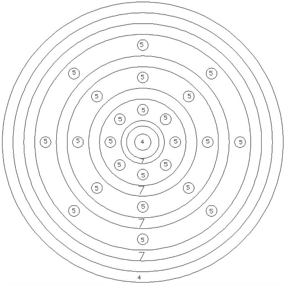
[0040] control figure 2 , to illustrate the specific technical solutions of the present invention. A micro-combustion thermal photovoltaic power generation device with heat recovery function, including: a casing, and placed in the casing: a fuel tank 1 for storing fuel, and the fuel can be selected from liquefied hydrogen, methane, and n-butane, which can also be used A mixture of several substances; a fuel flow regulating valve 2, which controls the flow of gasified fuel; a mixing chamber 3; an igniter 4, which uses piezoelectric materials to ignite by piezoelectric effect; 24 micro burners 5 arranged in parallel;

[0041] The thermo-photovoltaic panel 7 absorbs the thermal radiation energy of the wall surface of the micro-combustor and converts it into electric energy, using gallium antimonide GaSb or a material based on it.

[0042] Composite two-way gas channel 6, one of which is an exhaust gas discharge pipeline, connected to the exhaust outlet of the micro-burner; the ...


PUM


Abstract

The invention relates to a micro-combustion thermal-photovoltaic generating device with a regeneration function and aims to provide an electrical power generating system taking a micro-combustor as a heat resource and capable of converting thermal radiation into electric energy. The generating device comprises a shell, a fuel bin, a fuel flow regulator, a mix chamber, igniters, parallel N micro-combustors, thermal photovoltaic panels and a composite two-way airway, wherein the fuel bin is arranged in the shell and used for storing fuel, and the fuel flow regulator is used for controlling flow of the gasified fuel. Compared with the prior art, the micro-combustion thermal-photovoltaic generating device has the advantages that energy density is large by taking liquefied gas as the fuel, and sustainable working time of a system is long; part of waste heat is recycled by the adoption of the composite two-way airway, and thermal efficiency and stability of the system are improved.

Description

Technical field: [0001] The invention belongs to the technical field of micro-scale power generation, and more specifically relates to a micro-combustion thermal photovoltaic power generation device with a heat recovery function. Background technique: [0002] Burning fuel to generate energy is the most widely used energy utilization method in production and life. 90% of the world's energy is used directly or indirectly through combustion. But in some occasions, due to the limitation of processing technology, fuel combustion cannot play its role, such as portable electronic devices such as mobile phones and notebook computers. At present, people mainly rely on batteries to provide energy for them. Due to its small size and easy portability, chemical batteries have a lot of room for use in these occasions, but their disadvantages are also obvious, because of their low energy density and short continuous working time, they need to be replaced or charged frequently. Therefore...

Claims


Application Information

Patent Timeline
IPC IPC(8): F23D14/28F23D14/66H02S10/30
CPCY02E10/50Y02E20/34
Inventor 李君王源涛范皓龙李擎擎
Owner TIANJIN UNIV
Why Eureka
Try Eureka