Winding type permanent-magnet slip clutch and application thereof

A clutch and permanent magnet rotor technology, applied in the field of clutches, can solve the problems of eliminating braking torque, increasing actuators, cumbersome actuators, etc., and achieves the effects of large starting torque, simple control and excellent speed regulation performance.

Inactive Publication Date: 2014-11-05
JIANGSU MAGNET VALLEY TECH
View PDF2 Cites 14 Cited by
  • Summary
  • Abstract
  • Description
  • Claims
  • Application Information

AI Technical Summary

Problems solved by technology

Traditional clutches can be divided into chimeric clutches and friction clutches according to the working principle of the transmission of the engaging elements. According to the process of realizing the separation and closing actions, they can be divided into manipulation type and self-control type. According to the clutch operation mode, they can be divided into mechanical type, Pneumatic, hydraulic, electromagnetic, etc., all of the above traditional clutches have the disadvantages of friction, wear, or adding various cumbersome actuators to realize the clutching and closing functions.
An electromagnetic slip clutch solves the above problems well. The engagement and separation of the clutch are controlled by the on-off of the electric switch as in the present invention, but the electromagnetic slip clutch requires an additional rectifying circuit or a DC power supply. , when working, it needs to pass a DC current for a long time, and the effici

Method used


Image

  • Winding type permanent-magnet slip clutch and application thereof
  • Winding type permanent-magnet slip clutch and application thereof
  • Winding type permanent-magnet slip clutch and application thereof

Examples


Embodiment 1

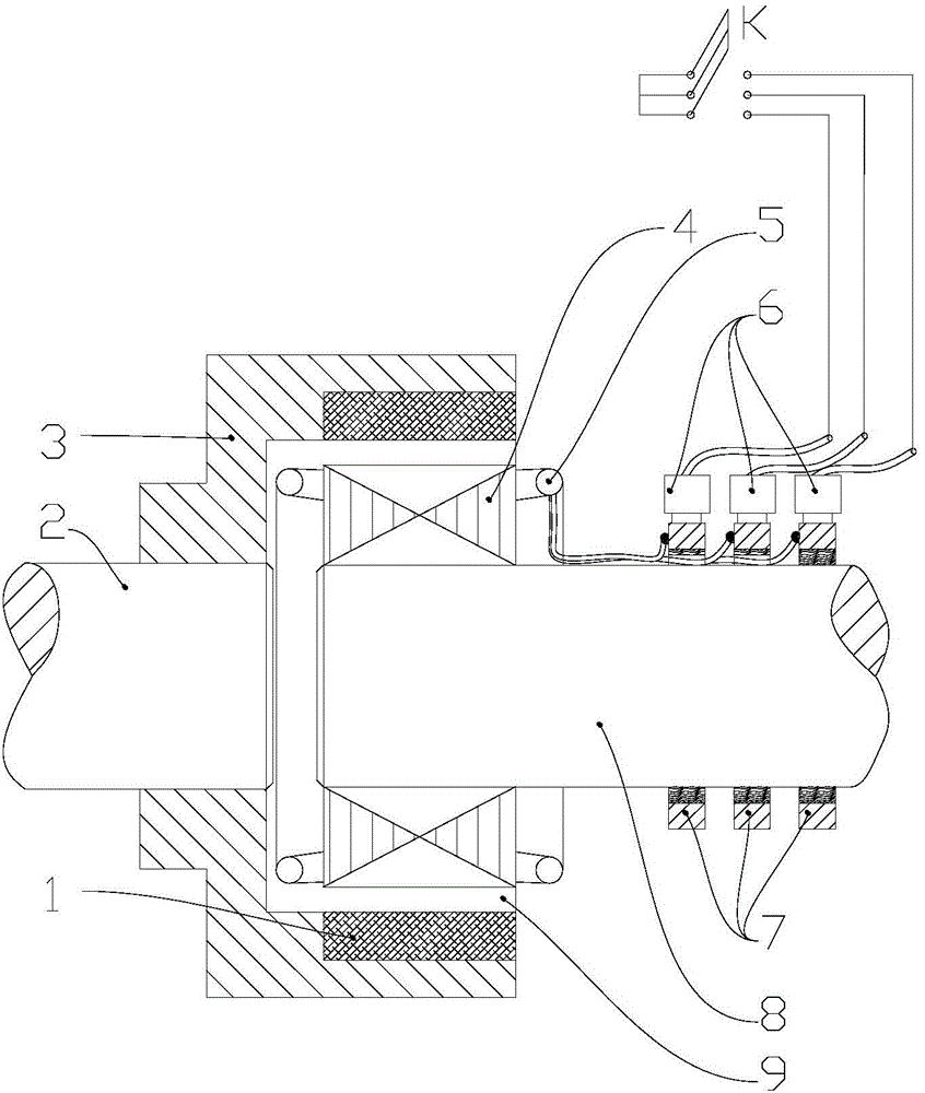
[0025] Embodiment one: figure 1 Shown is a most basic winding type permanent magnet slip clutch structure, the winding rotor and the permanent magnet rotor are coaxially arranged vertically, the permanent magnet rotor is installed on the first rotating shaft 2, the winding rotor is installed on the second rotating shaft 8, and the outer winding rotor The diameter is smaller than the inner diameter of the permanent magnet rotor; the permanent magnet rotor includes a permanent magnet 1 and a housing 3 that fixes the permanent magnet. The housing 3 is installed on the permanent magnet rotor shaft 2 8, and the N poles and S poles of the permanent magnets are alternately even on the housing 3. distribution; there is an air gap 9 between the permanent magnet rotor and the winding rotor, and the coil winding 5 can be one phase or multiple phases that can be connected symmetrically. The embodiment is a Y-shaped connection of three-phase windings. Optimum results require a series of me...

Embodiment 2

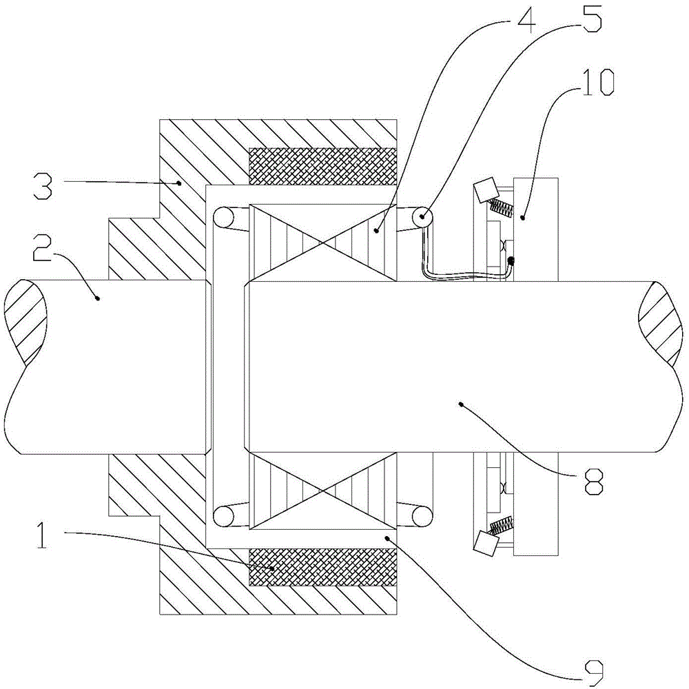
[0030] Embodiment two: in embodiment one, increase and set centrifugal switch 10, as figure 2 , the overspeed protection function can be realized. When the actual rotational speed exceeds the rotational speed set by the centrifugal switch 10, the counterweight of the centrifugal switch 10 deflects due to the centrifugal force, and the contact switch disconnects the coil winding 5, and the clutch is separated, realizing The function of the protection system; of course, it is also possible to set the speed sensor to give an overspeed signal, and then disconnect the electrical switch K to realize the overspeed protection function.

Embodiment 3

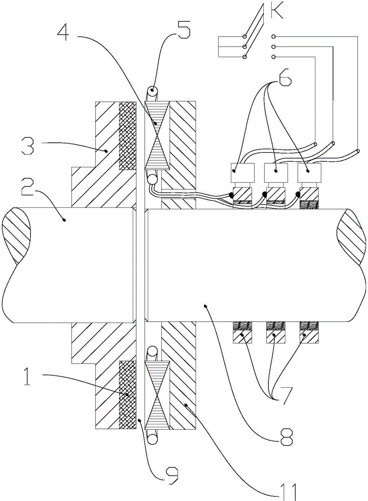
[0031] Embodiment 3: In Embodiment 1, the external switch K adopts an overcurrent protection switch. When the load increases, the current of the coil winding 5 of the winding rotor rises. When the current rises beyond the limit value, that is, the system is overloaded. The external switch trips, and the clutch Separation, automatic protection system function.


PUM


Abstract

The invention relates to a winding type permanent-magnet slip clutch. The winding type permanent-magnet slip clutch comprises a permanent-magnet rotor and a winding rotor coaxial with the permanent-magnet rotor. An air gap is reserved between the permanent-magnet rotor and the winding rotor. A slip ring and a carbon brush are arranged on a second rotating shaft and form a loop together with a coil winding, wherein switch-on or switch-off of the loop can be controlled by an electric switch. An induced current is generated in the coil winding through the slip between the two rotors, the coil winding with the current can be affected by electromagnetic force in the magnetic field of a permanent magnet, and then transmission of torque can be achieved; the electric switch controls switch-on or switch-off of the loop so as to control engagement or disengagement of the permanent-magnet slip clutch. The function of controlling engagement or disengagement of the clutch is achieved through switch-on or switch-off of the electric switch, and besides, the clutch has the overspeed protection function, the overload protection function, the soft start function and the good speed regulation function and can serve as a brake free of frictional contact.

Description

technical field [0001] The invention is a new structure of a frictionless clutch, which belongs to the category of clutches. During the working process, the clutch has no mechanical action, and the engagement and separation of the clutch are controlled by the on-off of the electric switch, and on this basis, overspeed protection, Overload protection, soft start, speed regulation and other functions, the fixed end can become a frictionless brake. Background technique [0002] A clutch is a device that can realize the engagement or separation function of the main and driven parts when transmitting motion and power on the coaxial line through various manipulation methods. Traditional clutches can be divided into chimeric clutches and friction clutches according to the working principle of the transmission of the engaging elements. According to the process of realizing the separation and closing actions, they can be divided into manipulation type and self-control type. According...

Claims


Application Information

Patent Timeline
IPC IPC(8): H02K49/10H02K49/02
CPCH02K49/06H02K51/00H02K1/223H02K16/005H02K2213/03H02K49/02H02K49/106
Inventor 漆复兴徐俊峰
Owner JIANGSU MAGNET VALLEY TECH
Why Eureka
Try Eureka