In-bed heat transfer tube for fluidized bed boiler

A technology for fluidized bed boilers and heat transfer tubes, applied to boiler water tubes, components of steam boilers, steam boilers, etc., can solve the problems of reduced heat transfer rate, poor durability, thicker diameter, etc., and achieve the suppression of tube wall thinning , Excellent durability, and the effect of improving heat transfer rate

Active Publication Date: 2014-11-05
EBARA ENVIRONMENTAL PLANT
View PDF6 Cites 7 Cited by
  • Summary
  • Abstract
  • Description
  • Claims
  • Application Information

AI Technical Summary

Problems solved by technology

However, in the structure disclosed in Patent Document 1, since the heat transfer tube is covered with a refractory material, the heat transfer rate is lowered and a large heat transfer area is required.
In addition, there is a disadvantage that the diameter of the heat transfer tube and the refractory becomes thick, and it is difficult to arrange the heat transfer tube
[0005] On the other hand, in Japanese Patent Application Laid-Open No. 7-217801 (Patent Document 2), a method of installing a protector and increasing the thickness of the heat transfer tube are proposed as a method of preventing the tube wall from being thinned due to wear of the heat transfer tube. The method of thickening the tube wall or spraying, but it is recorded that if a sheath is installed, there is a problem of greatly impairing heat transfer, and there is a problem of high cost in thickening the tube wall or spraying (refer to paragraph [0004]), pointing out that the previous Problems in tube wall thinning countermeasures, and a proposal to use high-chromium steel or stainless steel with good wear resistance for the heat transfer tube itself
However, in the method described in Patent Document 2, although the thinning of the pipe wall due to abrasion can be prevented, there is a problem of poor durability in an environment where the pipe wall is directly corroded by molten salt while being worn.

Method used


Image

  • In-bed heat transfer tube for fluidized bed boiler
  • In-bed heat transfer tube for fluidized bed boiler
  • In-bed heat transfer tube for fluidized bed boiler

Examples


Embodiment Construction

[0054] Below, refer to figure 1 Referring to FIG. 8, an embodiment of the heat transfer tube in the fluidized bed boiler of the present invention will be described. exist figure 1 In FIG. 8 , the same reference numerals are assigned to the same or corresponding components, and overlapping descriptions will be omitted.

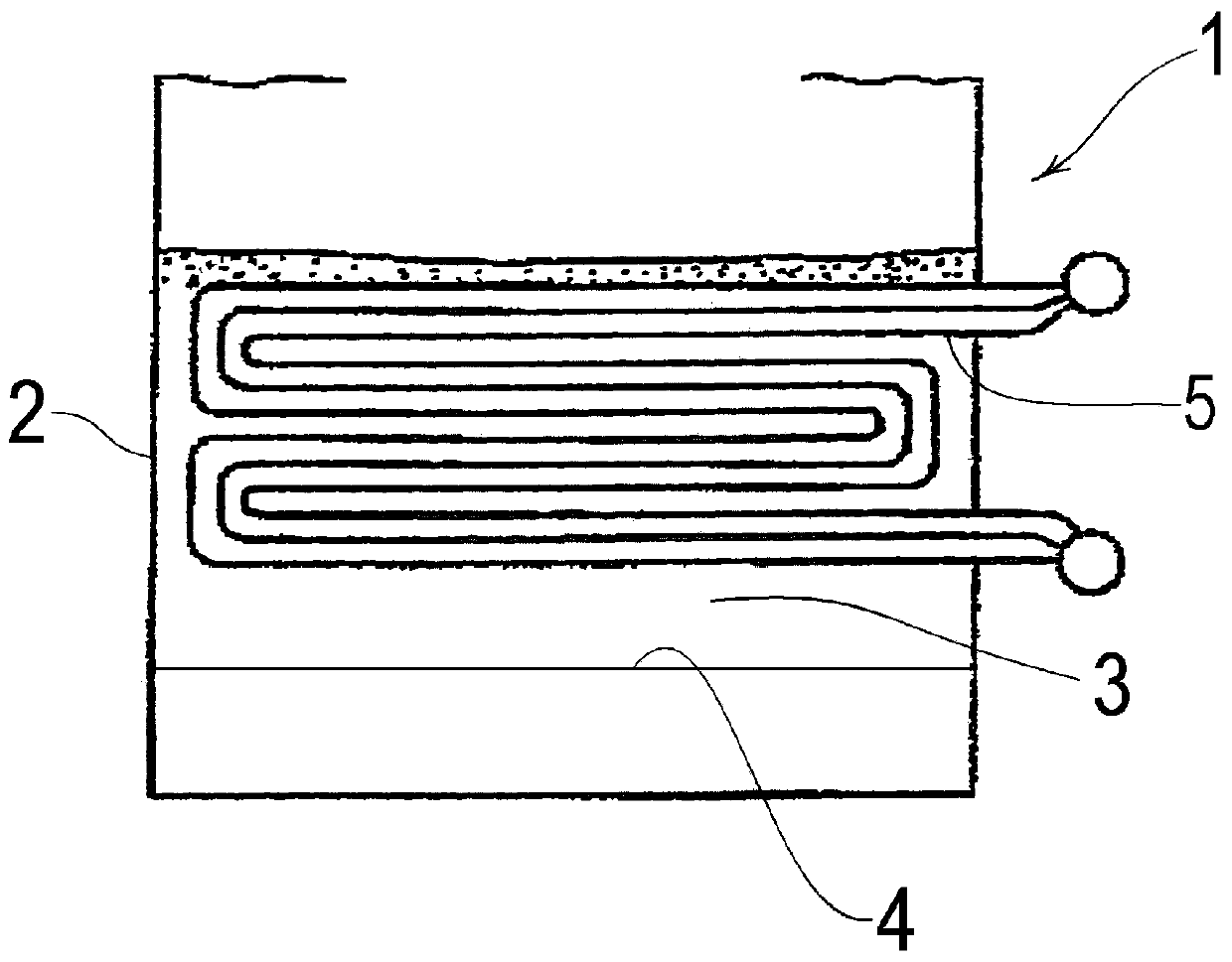
[0055] figure 1 It is a schematic cross-sectional view showing an embodiment of a fluidized-bed boiler provided with an intra-layer heat transfer tube of the present invention. Such as figure 1 As shown, a fluidized bed boiler 1 is provided with: a furnace body 2 having a substantially cylindrical shape or a substantially square cylindrical shape; a fluidized bed 3 for burning fuel such as waste or RDF; and a hearth floor 4 supporting the fluidized bed 3, and Layer 3 is provided with inner layer heat transfer pipes 5 . The fluidized bed 3 is filled with fluidized sand such as silica sand, that is, a fluidized medium, so as to bury the heat transfer tubes 5...


PUM

PropertyMeasurementUnit
thicknessaaaaaaaaaa

Abstract

The present invention pertains to an in-bed heat transfer tube installed in the fluidized bed of a fluidized bed boiler that burns fuels such as refuse-derived fuel (RDF) and waste with a high calorific value, including biomass and plastic, and recovers combustion heat. This in-bed heat transfer tube (5) for a fluidized bed boiler is installed in the fluidized bed (3) of the fluidized bed boiler (1), and the in-bed heat transfer tube (5) consists of: a water tube (6) through which a fluid flows; a protector (8) for protecting the water tube (6), said protector (8) being disposed on the outer circumferential side of the water tube (6); and a filler layer (7) disposed between the water tube (6) and the protector (8).

Description

technical field [0001] The present invention relates to an in-layer heat transfer tube installed in a fluidized layer of a fluidized-bed boiler that burns fuel such as RDF (refuse solidified fuel) or waste containing biomass or plastics with a high calorific value, and recovers and burns it hot. Background technique [0002] In recent years, effective use of energy has been sought from the viewpoint of coping with the rise in prices of fossil fuels, the problem of the greenhouse effect, and the like. Of these, the importance of power generation systems that burn RDF or waste as part of a thermal recycle has increased. In this power generation system, there is a method of recovering heat energy generated when RDF or waste is burned in a fluidized bed boiler through an in-layer heat transfer tube. In this method, when fuel such as RDF or waste is combusted by the fluidized bed boiler, since RDF or waste contains chlorine, a part of the chlorine is transferred to the fluid me...

Claims


Application Information

Patent Timeline
Patent Type & Authority Applications(China)
IPC IPC(8): F22B37/10F22B1/02F23C10/28F28F1/12F28F1/36
CPCF28D1/0477F23C10/18F28F1/30F28F1/36F23G5/30F23G7/12F28D2021/0024F22B31/0023F22B21/24F23C2206/103F28F19/06F28F1/124F28F1/003F23G7/10F22B37/107F28D13/00
Inventor 吉田裕阪本英之本田恭久
Owner EBARA ENVIRONMENTAL PLANT
Why Eureka
Try Eureka