
CARBON DIOXIDE RECOVERY SYSTEM AND OPERATING METHOD THEREOf

A carbon dioxide, recovery system technology, applied in chemical instruments and methods, separation methods, inorganic chemistry, etc., can solve the problems of reduced amine concentration and equipment performance, and achieve the effect of inhibiting the reduction of amine concentration, easy replenishment, and shortened stirring time.

Inactive Publication Date: 2014-11-12
KK TOSHIBA
View PDF8 Cites 5 Cited by
  • Summary
  • Abstract
  • Description
  • Claims
  • Application Information

AI Technical Summary

Problems solved by technology

On the other hand, solid amine requires long-term stirring and heating to dissolve in water, so it is difficult to replenish the absorption liquid in the system
Also, since this water is newly added to the absorption liquid in the system, the amine concentration of the absorption liquid may decrease, and the performance of the plant may decrease

Method used


Image

  • CARBON DIOXIDE RECOVERY SYSTEM AND OPERATING METHOD THEREOf
  • CARBON DIOXIDE RECOVERY SYSTEM AND OPERATING METHOD THEREOf

Examples


no. 1 approach

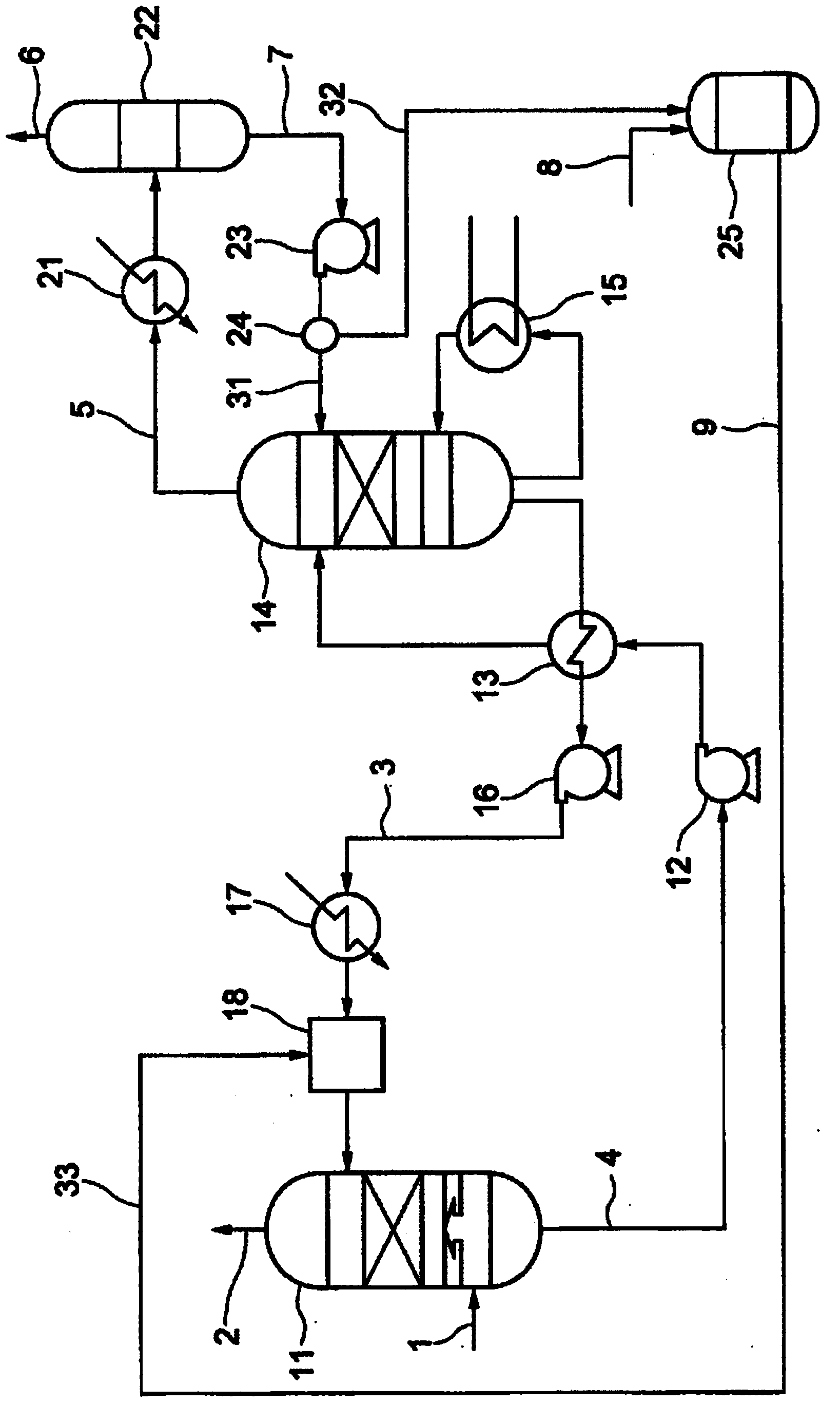
[0017] figure 1 It is a schematic diagram showing the configuration of the carbon dioxide recovery system of the first embodiment.

[0018] figure 1 The carbon dioxide recovery system of the first embodiment shown includes an absorption tower 11, a rich liquid pump (rich liquid pump) 12, a regeneration heat exchanger 13, a regeneration tower 14, a reboiler (reboiler) 15, a lean liquid pump (lean liquid pump) pump) 16, lean liquid cooler (lean liquid cooler) 17, buffer tank (buffer tank) 18, cooler 21, condenser 22, pump (pump) 23, switching valve 24 and mixer 25.

[0019] The absorption tower 11 is a carbon dioxide gas absorption tower. The absorption tower 11 makes the absorption tower inlet gas 1 containing carbon dioxide contact the absorption liquid, and makes the absorption liquid absorb carbon dioxide. Examples of the absorption tower inlet gas 1 include combustion exhaust gas generated in thermal power plants and the like. Examples of the absorbing liquid include am...

no. 2 approach

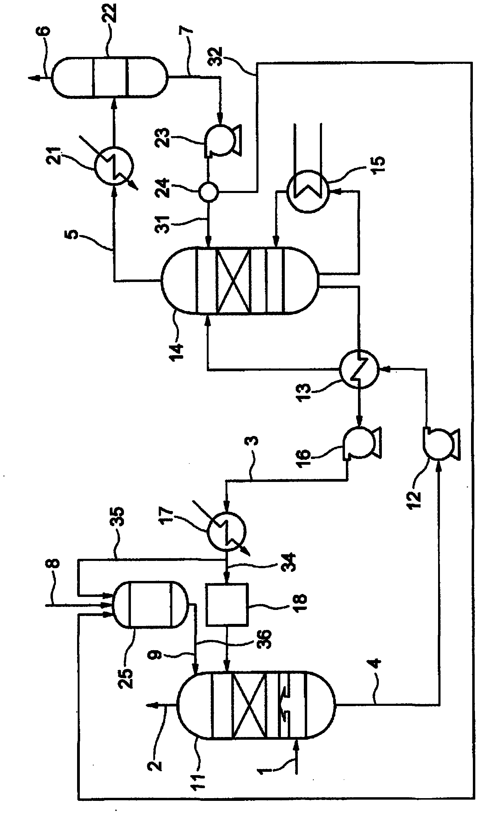
[0056] figure 2 It is a schematic diagram showing the configuration of the carbon dioxide recovery system of the second embodiment.

[0057] figure 2 The carbon dioxide recovery system of the second embodiment shown includes pipes 34 and 35 through which the lean liquid 3 discharged from the lean liquid cooler 17 circulates. The line 34 supplies the lean liquid 3 to the buffer tank 18 , and the line 35 supplies the lean liquid 3 to the mixer 25 . The mixer 25 supplies the make-up amine aqueous solution 9 directly to the absorption column 11 . The configuration other than that is the same as that of the first embodiment, and thus the description of the redundant configuration will be omitted.

[0058] The mixer 25 mixes the condensed water 7 , the make-up amine 8 from the outside, and the lean liquid 3 to generate the make-up amine aqueous solution 9 . The mixer 25 can mix the condensed water 7 , the make-up amine 8 and the lean liquid 3 at the same time. In addition, th...

Embodiment 1

[0065] Blow gas with a CO2 content rate of 99% into 100ml of water at 20°C at a flow rate of 100ml / min. After confirming that the outlet gas flow rate is equal to the inlet gas flow rate, add 10g of piperazine (piperazine) to the water. Stir with a stirrer until the piperazine dissolves. As a result, piperazine was completely dissolved in 10 minutes.


PUM


Abstract

A carbon dioxide recovery system includes an absorption tower in which carbon dioxide is absorbed into an absorbing solution then the absorbing solution is output to a regeneration tower in which carbon dioxide is released from the absorbing solution. The regeneration tower outputs the absorbing solution from which carbon dioxide has been released and an exhaust gas included released carbon dioxide and water vapor. In a condensing section the exhaust gas is separated into dioxide gas stream and a condensed water stream. In a mixing section the condensed water is mixed with an amine to a replenishment amine aqueous solution in which the amine is dissolved in the condensed water. In a replenishment section the absorbing solution is mixed with the replenishment amine aqueous solution.

Description

technical field [0001] Embodiments of the present invention relate to a carbon dioxide recovery system (system) and a method of operating the same. Background technique [0002] In recent years, the problem of global warming caused by the greenhouse effect of carbon dioxide (CO 2 ), which is a product of combustion of fossil fuels, has become larger. Against this backdrop, efforts are being made to study a method of separating and recovering carbon dioxide in combustion exhaust gas, and a method of storing the recovered carbon dioxide without releasing it into the atmosphere, targeting thermal power plants that use large amounts of fossil fuels. [0003] Specifically, there is known a carbon dioxide recovery system comprising: an absorption tower for bringing combustion exhaust gas into contact with an absorbing liquid so that the absorbing liquid absorbs carbon dioxide contained in the combustion exhaust gas; and a regeneration tower for heating the absorbing liquid that ha...

Claims


Application Information

Patent Timeline
Patent Type & Authority Applications(China)
IPC IPC(8): B01D53/78B01D53/96B01D53/62C01B32/50
CPCB01D53/96B01D53/62B01D53/1425B01D53/1475B01D2252/20436B01D2252/20447B01D2252/20457B01D2252/20484B01D2258/0283Y02C20/40B01D53/1493B01D2252/204B01D2257/504
Inventor 加藤康博村井伸次村松武彦齐藤聪
Owner KK TOSHIBA
Learn More