
Integrated modeling method for hypersonic flight vehicle engine body and internal contraction air inlet channel

A modeling method and hypersonic technology, applied in the fields of instruments, special data processing applications, electrical digital data processing, etc., can solve problems such as inability to actually design, complex modeling method parameters, and design methods remaining in basic configuration research, etc. To achieve the effect of convenient evaluation and simple modeling process

Inactive Publication Date: 2014-11-12
NORTHWESTERN POLYTECHNICAL UNIV
View PDF2 Cites 20 Cited by
  • Summary
  • Abstract
  • Description
  • Claims
  • Application Information

AI Technical Summary

Problems solved by technology

[0005] At present, in the research field of hypersonic vehicle design at home and abroad, there are mainly the following problems in the geometric modeling method of this type of vehicle. First, the modeling process cannot fully reflect the influence of the inlet on the aerodynamic shape of the hypersonic vehicle. It only stays in the basic configuration research and cannot be applied to actual design; second, the existing modeling methods have complex parameters, or focus on the design of the overall scheme, or based on the optimization of local details, but fail to give a comprehensive In addition, the original modeling method cannot use the geometric parameters directly related to the aerodynamic characteristics of the hypersonic vehicle, which makes the modeling process not intuitive enough
In addition, although some mature CAD software can realize complex geometric modeling functions, the basic idea is the size-driven principle, which is suitable for the design of individual small parts, but not suitable for the parametric design of highly integrated hypersonic aircraft

Method used


Image

  • Integrated modeling method for hypersonic flight vehicle engine body and internal contraction air inlet channel
  • Integrated modeling method for hypersonic flight vehicle engine body and internal contraction air inlet channel
  • Integrated modeling method for hypersonic flight vehicle engine body and internal contraction air inlet channel

Examples


Embodiment Construction

[0041] The present invention is described in detail below in conjunction with accompanying drawing and specific embodiment:

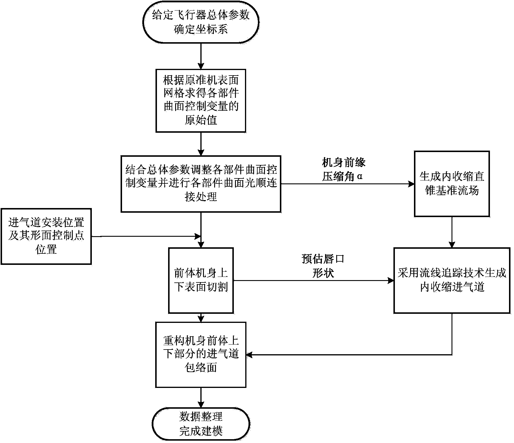
[0042] The flowchart of the overall modeling method of the present invention is as figure 1 shown.

[0043] Given the overall design index, determine the overall coordinate system:

[0044] The overall design parameters need to be given, including the length of the front body of the fuselage, the length of the rear body, the maximum width of the fuselage, the maximum thickness of the fuselage, the wing area, the aspect ratio, the tip ratio, the leading edge sweep angle and the inlet Control parameters. The coordinate system is selected as the rectangular coordinate system, the direction of the fuselage axis is the x direction, the wingspan direction is the y direction, and the z direction is the height direction of the aircraft. Determine the expression of the rectangular coordinate system

[0045] Solve for the control parameters of each block surfa...


PUM


Abstract

The invention provides an integrated modeling method for a hypersonic flight vehicle engine body and an internal contraction air inlet channel. The integrated modeling method comprises the following steps: (1) establishing a rectangular coordinate system, and constructing the surface mesh of an original quasi-flight vehicle engine body; (2) carrying out partitioning parameterization expression processing to each component of a flight vehicle to generate the geometric profile of each component; (3) combining the geometric positions of all components, and carrying out fairing processing to each component; (4) according to the installation position of the air inlet channel, cutting the upper surface and the lower surface of a flight vehicle forebody, and constructing the curved surface molded surface of the air inlet channel; (5) reconstructing the air inlet channel enveloping surfaces of the upper surface and the lower surface of the engine body to finish the integrated modeling of the hypersonic flight vehicle engine body and the air inlet channel. According to the method, the influence on the integral engine body configuration of the whole hypersonic flight vehicle by the geometric molded surface of an air inlet channel system is embodied, few control variables are used in a modeling process and can be flexibly regulated according to aerodynamic characteristics, and total expression precision is high.

Description

technical field [0001] The invention belongs to the field of hypersonic aircraft design, and relates to a geometric shape modeling method, in particular to a comprehensive modeling method for a hypersonic aircraft body and an inner shrinkage inlet. Background technique [0002] A hypersonic vehicle powered by a scramjet engine or a combined engine can achieve a rapid flight at a flight speed of Mach 5 or more at an altitude above 40Km, and has the advantages of fast flight speed, high flight altitude, strong defense penetration ability, and good survivability. With excellent characteristics, it can be widely used in many fields such as global rapid delivery of strategic weapons, high-altitude reconnaissance in theaters, and reusable space vehicles. Due to the harsh flight conditions of this type of aircraft, the airframe has extremely high requirements on aerodynamic force and aerodynamic heat, so the integrated design and manufacture of the airframe and air inlet is require...

Claims


Application Information

Patent Timeline
IPC IPC(8): G06F17/50
Inventor 蔡晋生王骥飞刘传振段焰辉
Owner NORTHWESTERN POLYTECHNICAL UNIV
Learn More