Vibration movement device for main shaft of numerical control electrochemical machining machine tool

A technology of electrolytic processing machine tools and motion devices, which is applied in the direction of electric processing equipment, electrochemical processing equipment, accessory devices, etc., can solve the problems of not being too large, small driving force, and impact force, etc., to reduce equipment costs and structure Simple, improve discharge effect

Active Publication Date: 2014-11-19
江西金匠智能装备有限公司
View PDF4 Cites 19 Cited by
  • Summary
  • Abstract
  • Description
  • Claims
  • Application Information

AI Technical Summary

Problems solved by technology

[0005] The vibration electrolytic machining mechanism is mostly used in the crank slider mechanism and electromagnetic drive mode. The crank slider mechanism is difficult to achieve high-frequency machining, and the amplitude adjustment is difficult, and there is impact force in the process; electromagnetic drive can achieve high frequency, but the structure is complicated. , the driving force is small, and the load cannot be too large, so the application fields of these two mechanisms are limited

Method used


Image

  • Vibration movement device for main shaft of numerical control electrochemical machining machine tool
  • Vibration movement device for main shaft of numerical control electrochemical machining machine tool
  • Vibration movement device for main shaft of numerical control electrochemical machining machine tool

Examples


Embodiment Construction

[0030] The present invention will be described in further detail below in conjunction with the accompanying drawings.

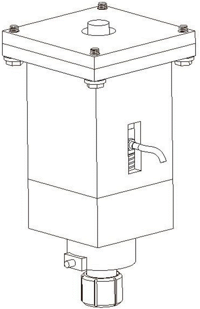
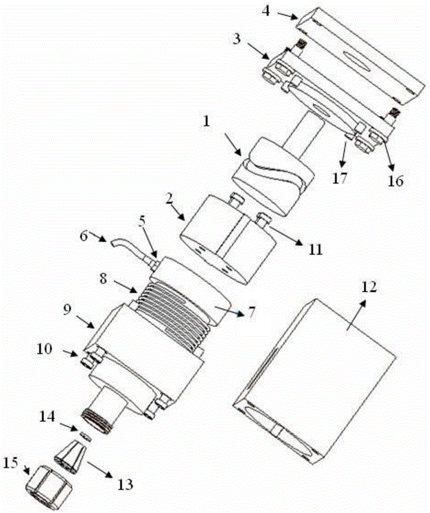
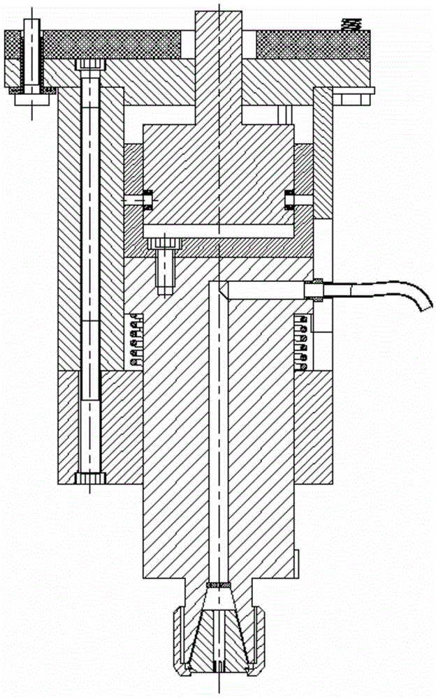
[0031] As a preferred embodiment, the structure of the vibrating motion device for the spindle of the CNC electrolytic machining machine tool of the present invention is as follows: Figure 1-3 As shown, it includes space cam 1, cam guide sleeve 2, vibration shaft 7, guide sleeve 9, guide housing 12, end cover 3, insulating plate 4, quick connector 5, electrolyte inlet pipe 6, support spring 8, sealing ring 14 , Spring collet 13, lock nut 15, insulating bolt 16 and so on.

[0032] The structure of space cam 1 is as follows Figure 4 As shown, its upper part is the torque input shaft 1-1, and the guide groove 1-2 of the space cam 1 is a symmetrical sine wave groove;

[0033] The structure of the cam guide sleeve 2 is as follows: Figure 5 As shown, its interior is hollow, and its diameter matches the outer diameter of the space cam 1. There are two sliding ...


PUM


Abstract

The invention discloses a vibration movement device for a main shaft of a numerical control electrochemical machining machine tool, and belongs to the field of electrochemical machining. The vibration movement device comprises a space cam, a cam guide sleeve, a guide shell and a vibration device. The space cam comprises a transmission input shaft and a guide groove, wherein the transmission input shaft is connected with the main shaft of the numerical control electrochemical machining machine tool, and the guide groove is a symmetrical sine wave groove. The cam guide sleeve is internally provided with a sliding cam pin protruding inwards, and is located in the guide groove of the space cam after being installed, and a guide rail is arranged on the outer side of the cam guide sleeve. Linear guide grooves which are symmetrically distributed are formed in the guide shell, and the guide rail of the cam guide sleeve is located in the linear guide grooves after the guide shell is installed. The vibration movement device for the main shaft of the numerical control electrochemical machining machine tool is simple in structure, the cost of the vibration movement device can be reduced easily, large loads, frequency and amplitude can be adjusted, electrolyte can be sprayed to a machining area from the interior of a cathode, discharging of electrolysate produced in electrochemical machining can be effectively improved, and the precision of the numerical control electrochemical machining can be improved.

Description

technical field [0001] The invention relates to a vibrating motion device for a spindle of a numerically controlled electrolytic machining machine tool, belonging to the field of vibrating electrolytic machining devices. Background technique [0002] Electrolytic machining is a special processing technology, which is a processing method that uses the principle of electrochemical anodic dissolution to remove materials. CNC electrolytic machining technology is a combination of numerical control technology and electrolytic machining technology. It uses the method of anode dissolution to make the anode of the workpiece installed on the CNC machine tool and the cathode of the tool relatively follow the CNC trajectory, so that the workpiece can be processed into the desired shape. It has both CNC machining It is flexible and has the advantages of electrolytic machining. It can process difficult-to-machine materials quickly, with good surface quality and no loss of tool cathodes. I...

Claims


Application Information

Patent Timeline
Patent Type & Authority Applications(China)
IPC IPC(8): B23H3/00B23H11/00
Inventor 徐波干为民褚辉生房汝建夏任波吴志伟
Owner 江西金匠智能装备有限公司
Why Eureka
Try Eureka