Integrated forming die and method for glass fiber reinforced plastic antenna housing

A glass fiber reinforced plastic radome and molding die technology, applied in the field of glass fiber reinforced plastic radome molding, can solve the problems of difficult gluing precision control, fiber damage, numerous processing procedures, etc., so as to eliminate manual grinding or mechanical processing procedures and reduce operation difficulty. , Improve the effect of bonding effect

Active Publication Date: 2014-11-19
NO 20 RES INST OF CHINA ELECTRONICS TECH GRP
View PDF6 Cites 13 Cited by
  • Summary
  • Abstract
  • Description
  • Claims
  • Application Information

AI Technical Summary

Problems solved by technology

[0004] (1) Due to the use of prepreg materials, when the metal parts used in the assembly of the radome are placed into the radome, the method currently generally used is the insertion method of mechanical drilling and secondary bonding after the radome is formed. This method leads to many processing procedures after the radome is formed, especially the quality of the bonding in the secondary bonding is greatly affected by human factors, and it is difficult to control the accuracy of the bonding
[0005] (2) After the radome is formed, manual grinding or mechanical processing is required to meet the appearance quality requirements and dimensional accuracy requirements of the product, which not only increases the processing procedures after the radome is formed, but also has different degrees of fiber damage during the processing. Affect the mechanical properties of high-performance radome products
However, the structural form of the radome has been confirmed and cannot be changed. Therefore, only a new radome forming process plan is proposed.

Method used


Image

  • Integrated forming die and method for glass fiber reinforced plastic antenna housing
  • Integrated forming die and method for glass fiber reinforced plastic antenna housing
  • Integrated forming die and method for glass fiber reinforced plastic antenna housing

Examples


Embodiment Construction

[0023] Describe the present invention below in conjunction with specific embodiment:

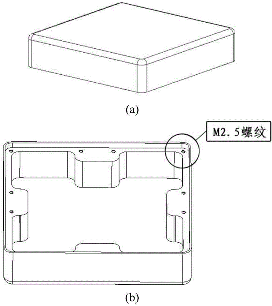
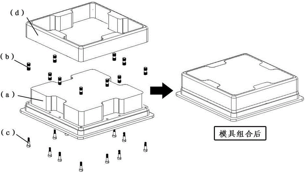
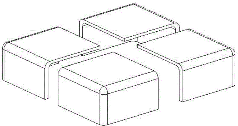
[0024] Refer to attached figure 2 , The integrated forming mold is composed of main mold (a), embedded round nut (b), special screw (c), glass fiber reinforced plastic skeleton (d) and outer mold (e). The main mold (a) is provided with a positioning hole and a demoulding hole, and the special screw (c) passes through the positioning hole to install and position the embedded round nut (b) on the main mold (a); There is an insertion hole for the embedded round nut (b), and there is a gap between the hole wall and the embedded round nut (b). The purpose is: when the radome is molded in the autoclave equipment, the high temperature resin will Under the action of impregnation and capillary force, the gap is automatically filled to achieve the purpose of synchronously bonding the embedded round nut (b) into the radome; the outer mold (e) is composed of four parts, which are combined to form a T...


PUM


Abstract

The invention relates to an integrated forming die and method for a glass fiber reinforced plastic antenna housing. The integrated forming die is composed of a main die (a), embedded circular nuts (b), special screws (c), a glass fiber reinforced plastic framework (d) and an outer die (e). A forming process comprises the following steps: (1) doing preparation work and assembling the dies; (2) preparing raw materials; (3) laying; (4) forming the antenna housing by an autoclave; and (5) releasing the dies and carrying out post-treatment. By adopting the integrated forming die, the embedded circular nuts (b) are synchronously glued and arranged in the forming process of the antenna housing and cracks caused by mechanical drilling when the embedding circular nuts are arranged by adopting a conventional method are avoided; drilling and secondary gluing procedures are eliminated, the operation difficulty is reduced and the splicing effect of the embedded circular nuts (b) is improved; and the main die (a) and the outer die (e) are combined so that the appearance quality requirements and the size precision requirements on the antenna housing are met when the antenna housing is formed and a manual polishing or machining procedure in a conventional forming method is eliminated.

Description

technical field [0001] The invention relates to a forming technology of a glass fiber reinforced plastic radome, in particular to an integrated forming mold and a forming method of a glass fiber reinforced plastic radome. Background technique [0002] The main function of the radome is to protect the antenna system inside the hood from external damage and destruction, and has functions such as wave penetration, heat resistance, rain erosion resistance, weather resistance, load bearing, impact resistance, and air tightness. High-performance radome is usually formed by autoclave equipment. Since the autoclave forming equipment can strictly control the temperature, pressure, time and other factors of the radome during the molding process, it can also vacuumize and apply external pressure, so the resin of the radome Uniform distribution and compact structure. At the same time, the raw material of high-performance radome usually adopts continuous glass fiber prepreg. Continuous ...

Claims


Application Information

Patent Timeline
Patent Type & Authority Applications(China)
IPC IPC(8): B29C33/00B29C70/44B29C33/58B29C33/72
Inventor 杨尚杰徐琳
Owner NO 20 RES INST OF CHINA ELECTRONICS TECH GRP
Why Eureka
Try Eureka