Activated carbon packing machine
A packing machine and activated carbon technology, which is applied in packaging, transportation and packaging, and the type of packaged items, etc., can solve the problems of low packing efficiency and affecting the health of packing personnel, and achieve high packing efficiency, simple and practical structure, and good effect Effect
- Summary
- Abstract
- Description
- Claims
- Application Information
AI Technical Summary
Problems solved by technology
Method used
Image


Examples
Embodiment Construction
[0021] The present invention will be further described below in conjunction with the accompanying drawings.
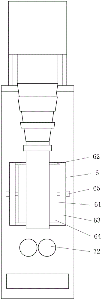
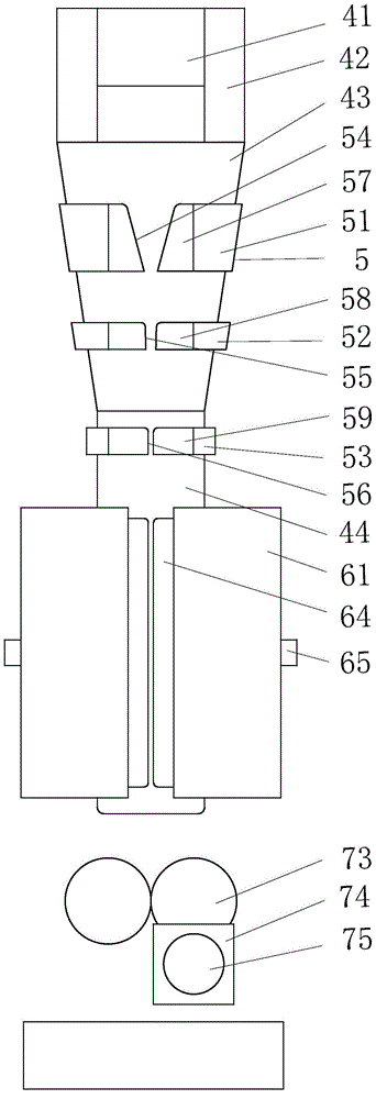
[0022] as attached figure 1 attached Figure 5 As shown: a kind of activated carbon dispensing machine, comprising a mounting seat 3 provided with a vertical plate 31, located at the front side of the vertical plate 31 and surrounded by a feeding pipe 4 with a feed hopper 41 screwed to the mounting seat 3, set Outside the feed pipe 4 and the rear end is provided with a guide sleeve 5 that runs through the guide grooves at the upper and lower ends and two guide blocks that are respectively connected to the rear end of the guide sleeve 5 and the mounting seat 3, and are located in the side seal below the feed pipe 4 in turn. Device 6, non-woven fabric tube transfer device 7 and end seal cutting device 8, quantitative feeding device 9 located above the feed hopper 41, steering roller 1 located above the feed pipe 4 with the axis horizontally arranged and parallel to the ...
PUM
 Abstract
Description
Claims
Application Information
 - Generate Ideas
- Intellectual Property
- Life Sciences
- Materials
- Tech Scout
- Unparalleled Data Quality
- Higher Quality Content
- 60% Fewer Hallucinations
Browse by: Latest US Patents, China's latest patents, Technical Efficacy Thesaurus, Application Domain, Technology Topic, Popular Technical Reports.
© 2025 PatSnap. All rights reserved.Legal|Privacy policy|Modern Slavery Act Transparency Statement|Sitemap|About US| Contact US: help@patsnap.com