Cushion rubber coiling device for tire production

A pad rubber and tire technology, which is applied in the direction of winding strips, transportation and packaging, thin material processing, etc., can solve the problems of large space occupation, two pads sticking together, easy to pack, etc., and achieve large bearing capacity of the guide rail , Improve production efficiency and reduce labor intensity

Inactive Publication Date: 2014-11-19
SAILUN GRP CO LTD
View PDF9 Cites 3 Cited by
  • Summary
  • Abstract
  • Description
  • Claims
  • Application Information

AI Technical Summary

Problems solved by technology

[0004] Cushion rubber is one of the main semi-finished parts in tire production. In the existing technology, the production of cushion rubber needs to use a linkage line. The final compound rubber is fed into the extruder through the barrel of the compound extruder, and then passed through the extruder head. The mouth shape extrudes the rubber material into the desired shape and size of the side section. At this time, the temperature of the semi-finished product is high and the shape is not easy to maintain, so a long linkage line is required for cooling and transportation. The semi-finished product enters the spraying section for cooling. Good rubber pads need to be stored and transported. In the storage and transportation stage, the rubber pads in the semi-finished workshop are generally cut with a composite line, manually picked up one by one and placed in the 100-page car, and then transported to the molding workshop and then put the pads in Adhesive pad feeding rack, every time molding needs to put pad rubber on the feeding rack, the labor is complicated, and the 100-page cart is complicated to transport and takes up a lot of space
When the pad glue cut by the semi-finished product workshop is stored in the molding workshop, the number of cutting sections is large and the sections will be slightly bent, the quality of the joints is not good, and it is easy to pack, which affects the uniformity of the embryo
[0005] At the same time, the coiling station that comes with the original equipment is also used to complete the curling of the pad rubber. Because two pads are extruded at the same time, there may be reasons why the two pads are out of sync when rolling, resulting in two Adhesion, roll deviation, and messy roll between pads

Method used


Image

  • Cushion rubber coiling device for tire production
  • Cushion rubber coiling device for tire production
  • Cushion rubber coiling device for tire production

Examples


Embodiment Construction

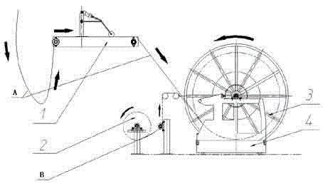
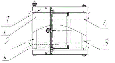
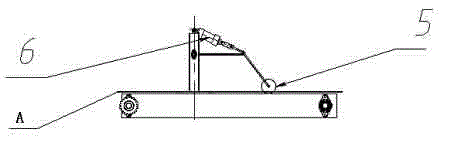
[0033] The specific embodiment of the present invention is described according to accompanying drawing now, as Figure 1~5 as shown,

[0034] A pad rubber rolling device for tire production, comprising: a pad rubber transition device 1, a pad cloth guiding device 2, an I-shaped wheel 3 and a pad rubber rolling trolley 4, the pad rubber transition 1 and the pad cloth guiding device The equipment 2 outputs the pad rubber A and the pad cloth B to the I-shaped wheel respectively, and when the I-shaped wheel rotates, the pad rubber A and the pad cloth B are curled into the I-shaped wheel 3 at the same linear speed , wherein, the cushion rubber B is closer to the axle of the I-shaped wheel 3 than the pad A, that is, the pad B surrounds the pad A from the outside to prevent the gap between the two layers of pad A. sticky. At the same time, the crimping of the I-shaped wheel makes the transportation and storage mode of the pad rubber change from being cut into a single strip to bein...


PUM


Abstract

The invention provides a cushion rubber coiling device for tire production. The cushion rubber coiling device comprises a cushion rubber transition device, a cloth liner unwinding device, a spool and a cushion rubber coiling cart, the cushion rubber transition device receives semi-finished cushion rubber and conveys the same to the spool, the cloth liner unwinding device outputs cloth liners to the spool which is arranged on the cushion rubber coiling cart, and the spool has rotational degree of freedom relative to the cushion rubber coiling cart and drives the cushion rubber and the cloth liners to enter the spool at the same linear speed in a coiling manner when rotating. The cushion rubber coiling device has the advantages that the cushion rubber is outputted synchronously without adhesion and warping and few in conveying cut surfaces being coiled by the spool, quality of the cushion rubber is effectively guaranteed, and production efficiency is improved.

Description

[0001] technical field [0002] The invention relates to a tire product equipment device, in particular to a pad rubber rolling device in the tire production process. [0003] Background technique [0004] Cushion rubber is one of the main semi-finished parts in tire production. In the existing technology, the production of cushion rubber needs to use a linkage line. The final compound rubber is fed into the extruder through the barrel of the compound extruder, and then passed through the extruder head. The mouth shape extrudes the rubber material into the desired shape and size of the side section. At this time, the temperature of the semi-finished product is high and the shape is not easy to maintain, so a long linkage line is required for cooling and transportation. The semi-finished product enters the spraying section for cooling. Good rubber pads need to be stored and transported. In the storage and transportation stage, the rubber pads in the semi-finished workshop ar...

Claims


Application Information

Patent Timeline
Patent Type & Authority Applications(China)
IPC IPC(8): B65H18/08B65H20/14B65H23/04
Inventor 李祥锋程恭朱端端景泉
Owner SAILUN GRP CO LTD
Why Eureka
Try Eureka