Topological structure of multi-level photovoltaic power generation system and control method of topological structure

A photovoltaic power generation system and topological structure technology, applied in photovoltaic power generation, electrical components, single-network parallel feeding arrangement, etc., can solve large switching loss and conduction loss, large power frequency step-up transformer, difficult large-scale photovoltaic Array unified control and other issues

Inactive Publication Date: 2014-11-19
UNIV OF ELECTRONICS SCI & TECH OF CHINA
View PDF8 Cites 37 Cited by
  • Summary
  • Abstract
  • Description
  • Claims
  • Application Information

AI Technical Summary

Problems solved by technology

[0004] The technical problem to be solved by the present invention is that the power frequency step-up transformer used in the prior art when the large-scale photovoltaic power generation system is connected to the power grid is large in size and high in cost, and it is difficult to uniformly control the large-scale photovoltaic array, and the large-scale The two-level voltage source inverter with capacity has large current, large switching loss and conduction loss, etc., so a multi-level photovoltaic power generation system topology and its control method are proposed

Method used


Image

  • Topological structure of multi-level photovoltaic power generation system and control method of topological structure
  • Topological structure of multi-level photovoltaic power generation system and control method of topological structure
  • Topological structure of multi-level photovoltaic power generation system and control method of topological structure

Examples


Embodiment Construction

[0075] The embodiments of the present invention will be further described below in conjunction with the accompanying drawings. This embodiment is implemented on the premise of the technical solution of the present invention, and detailed implementation methods and specific operating procedures are provided, but the protection scope of the present invention is not limited to Examples described below.

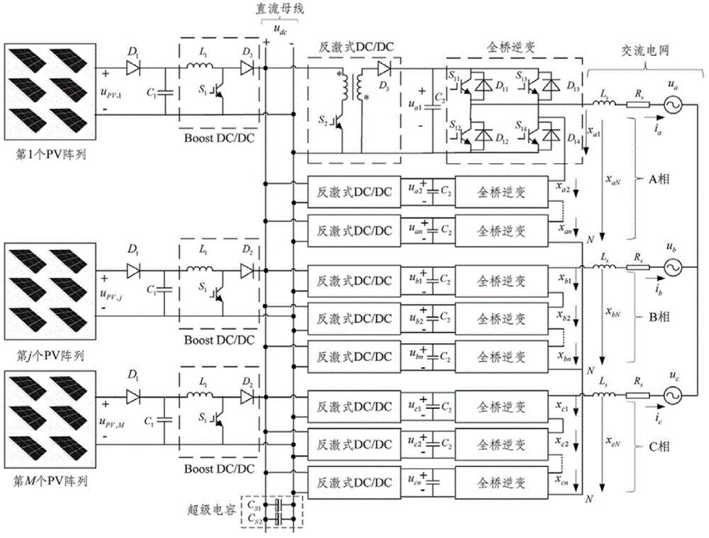
[0076] figure 1 It is a structural block diagram of a multi-level photovoltaic power generation system topology according to an embodiment of the present invention, including M photovoltaic arrays and their step-up DC / DC converters, 3n isolated flyback DC / DC converters, and 3n An H-bridge voltage source inverter, the positive poles of the photovoltaic array are connected to the unified DC bus u through their respective step-up DC / DC converters dc The positive pole is connected, and the negative pole is connected to the unified DC bus u through their respective step-up DC / DC conv...


PUM


Abstract

The invention relates to a topological structure of a multi-level photovoltaic power generation system and a control method of the topological structure. The topological structure comprises M photovoltaic arrays, the boost DC / DC (direct current / direct current) converters of the M photovoltaic arrays, 3n isolation flyback DC / DC converters and 3n H-bridge voltage source inverters. The PWM (pulse-width modulation) control signals of the first to nth H-bridge voltage source inverters of the three phases A, B and C of the cascade H-bridge multi-level voltage source inverters are obtained through an active power calculation method of a super-capacitor direct-current bus voltage controller and a photovoltaic array, and current tracking control of a dq synchronous coordinate system; the PWM control signals of the electronic power switches S2 of the wth and kth isolation flyback DC / DC converters are obtained through a control method of the isolation flyback DC / DC converters; the PWM control signals of the electronic power switches S1 of the j boost DC / DC converters are obtained through a control method of the boost DC / DC converters. The topological structure has the benefits that the shortcomings of large volume and high cost of power-frequency boosting transformers used when existing large-scale photovoltaic power generation systems are connected to a power grid are overcome.

Description

technical field [0001] The invention belongs to the technical field of photovoltaic power generation grid connection, relates to the technical field of a multi-level photovoltaic power generation system topology and its control technology, and specifically relates to a multi-level photovoltaic power generation system topology and a control method thereof. Background technique [0002] Photovoltaic power generation technology is an important part of the field of new energy power generation technology. With the rapid development of power electronics technology and digital signal processor technology, photovoltaic grid-connected power generation technology has gradually entered into practical use. With the increasing penetration of new energy and distributed power generation in the power system, large-scale photovoltaic power generation technology marked by new topology and new control strategy has become a research hotspot in academia and industry. In 1981, Nabae et al. propos...

Claims


Application Information

Patent Timeline
Patent Type & Authority Applications(China)
IPC IPC(8): H02J3/38H02M7/5387
CPCY02E10/56
Inventor 韩杨
Owner UNIV OF ELECTRONICS SCI & TECH OF CHINA
Why Eureka
Try Eureka