Rotational flow type fluidized bed crystallizer

A technology of fluidized bed and crystallizer, which is applied in the field of crystallization of chemical engineering, can solve the problems of unsatisfactory crystal shape and particle size distribution of crystallized products, and achieve the effect of being conducive to popularization and use, narrow particle size distribution and neat appearance

Inactive Publication Date: 2014-11-26
SICHUAN UNIV
View PDF4 Cites 12 Cited by
  • Summary
  • Abstract
  • Description
  • Claims
  • Application Information

AI Technical Summary

Problems solved by technology

For example, in the paper "Experimental Research on the Crystallization of Sandy Aluminum Hydroxide in a Spouted Fluidized Bed" published by Zhao Kun and others, the application of the spouted fluidized bed in the crystallization process was studied (see "Sichuan Metallurgy", Volume 33, No. 2, 63-66 pages), but the crystallization fluidized bed is limited to the traditional fluidized process, the turbulence inside the bed is severe, the secondary nucleation is still strong, and the crystal shape and particle size distribution of the crystallization product are still not ideal

Method used


Image

  • Rotational flow type fluidized bed crystallizer
  • Rotational flow type fluidized bed crystallizer
  • Rotational flow type fluidized bed crystallizer

Examples


Embodiment 1

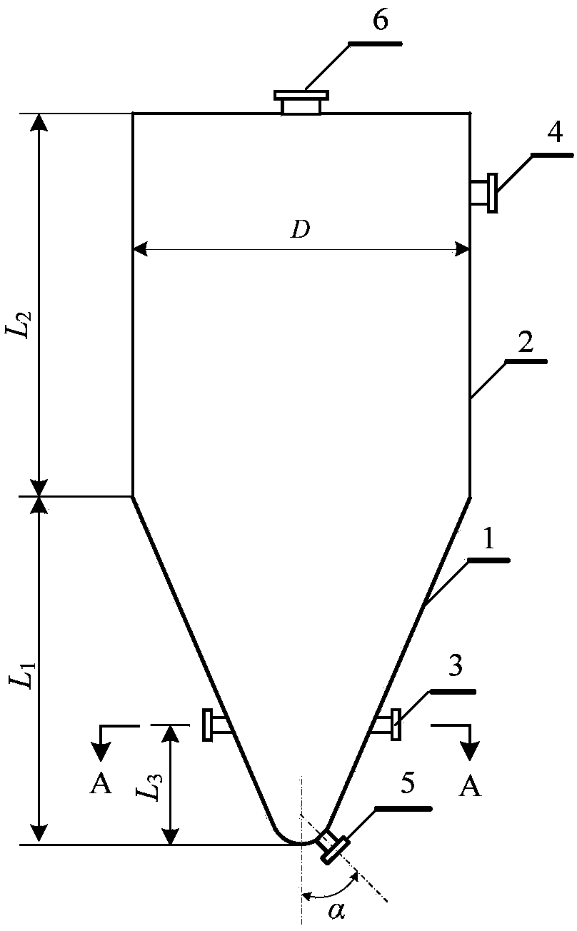
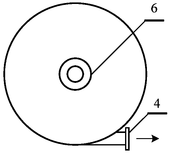
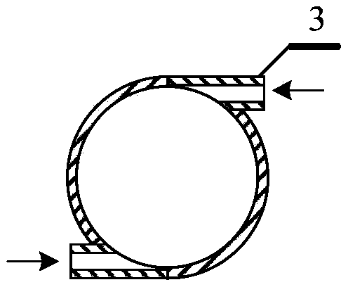
[0030] In this embodiment, the structure of the swirling fluidized bed crystallizer is as follows figure 1 As shown, it is composed of a bed body, the bed body is a combination of a stainless steel cylinder 2 and a stainless steel conical cylinder 1, the inner diameter of the large end of the conical cylinder is the same as that of the cylinder, and the cone top of the conical cylinder is a circular Arc-shaped, the conical cylinder 1 is located below the cylinder 2, and its large end and the lower end of the cylinder are welded to form an integrated structure. When welding, the axes of the cylinder 2 and the cone 1 should be coincident; the cylinder The upper end of the body 2 is closed, and the closed end surface is provided with a seed crystal inlet 6, and the side wall of the lower section of the conical cylinder 1 is provided with a feed pipe 3 for adding the feed liquid. There are two feed pipes surrounding the conical cylinder The same height is distributed 180° apart, ...

Embodiment 2

[0035] In this embodiment, the structure of the swirling fluidized bed crystallizer is as follows Figure 4 As shown, it consists of a bed body and a cooling jacket 9 . The bed body is a combination of a stainless steel cylinder 2 and a stainless steel conical cylinder 1, the inner diameter of the large end of the conical cylinder is the same as that of the cylinder, the top of the conical cylinder is arc-shaped, and the conical cylinder 1 is located at Below the cylindrical body 2, its large end and the lower end of the cylindrical body form an integrated structure by welding. When welding, the axes of the cylindrical body 2 and the conical cylindrical body 1 should be coincident; the upper end of the cylindrical body 2 is closed, and the closed The end face is provided with a seed crystal feeding port 6, and the side wall of the lower section of the conical cylinder body 1 is provided with a feed pipe 3 for adding feed liquid. The feeding pipes are all located in the horizo...

Embodiment 3

[0040] In this embodiment, the swirling fluidized bed crystallizer in Example 2 is combined with other equipment into a batch crystallization system, and its structure is shown in Figure 6 ,From Figure 6 It can be seen that the batch crystallization system includes a swirling fluidized bed crystallizer 10 , a circulation pump 11 , a batching tank 12 , a liquid-solid separator 13 and a mother liquor storage tank 14 . The liquid inlet pipe of the circulation pump 11 is connected with the discharge pipe that constitutes the bed body of the swirl type fluidized bed crystallizer 10 through a pipe fitting, and the liquid outlet pipe of the circulation pump 11 is connected with the composition of the swirl type fluidized bed crystallizer 10 through a pipe fitting. The feed pipe provided on the bed body is connected, the batching tank 12 is placed at a high position, and its discharge port is connected to the pipe fitting connected to the liquid outlet pipe of the circulating pump 1...


PUM

PropertyMeasurementUnit
angleaaaaaaaaaa
particle sizeaaaaaaaaaa

Abstract

The invention discloses a rotational flow type fluidized bed crystallizer. The rotational flow type fluidized bed crystallizer comprises a bed body, wherein the bed body is formed by combining a cylinder and a cone cylinder; the inner diameter of the large end of the cone cylinder is equal to that of the cylinder; the cone top of the cone cylinder is of a circular arc shape; the cone cylinder is positioned below the cylinder; the large end of the cone cylinder is connected with the lower end of the cylinder; the upper end of the cylinder is closed; a seed crystal adding opening is formed in the end surface of the upper end of the cylinder; at least two feeding pipes for adding material liquid are arranged on the side wall of the lower section of the cone cylinder and are uniformly distributed around the cone cylinder at the same height; each feeding pipe is positioned in the horizontal tangential direction of the cone cylinder; a crystal outlet is formed in the cone top of the lower end of the cone cylinder; a discharging pipe for outputting mother liquid is arranged on the side wall of the upper part of the cylinder and is positioned in the horizontal tangential direction of the cylinder, and an outlet of the discharging pipe is in accordance with the rotational direction of rotational flow formed by the material liquid. In order to meet requirements of a clearance crystallization process, a cooling jacket can be arranged on the basis of the structure.

Description

technical field [0001] The patent of the invention belongs to the technical field of crystallization of chemical engineering, and relates to a crystallizer. Background technique [0002] Crystallization is a unit operation in the preparation of chemical products. The stirred tank crystallizer is a commonly used crystallizer. Because the stirring blades of this type of crystallizer have a strong crushing effect on the crystal, the secondary nucleation rate is high, and the crystallized product The particle size is small, the particle size distribution is wide, and the crystal morphology is poor, which makes it difficult to meet the requirements of some chemical products. [0003] Theoretically speaking, to obtain crystalline products with uniform particle size and neat crystal shape, controlling the secondary nucleation is the key. For this reason, some researchers have used fluidization technology in the crystallization process to avoid the breaking of the crystal by the st...

Claims


Application Information

Patent Timeline
Patent Type & Authority Applications(China)
IPC IPC(8): B01D9/02
Inventor 叶世超李俊宏沈月音
Owner SICHUAN UNIV
Why Eureka
Try Eureka