Manufacturing method of automotive interior roof

A technology for automobile interior decoration and manufacturing method, which is applied to the manufacturing field of automobile interior decoration ceiling, and can solve the problems of high investment in equipment and tooling molds, small product thickness, consumption, etc.

Active Publication Date: 2016-02-03
GREAT WALL MOTOR CO LTD
View PDF4 Cites 0 Cited by
  • Summary
  • Abstract
  • Description
  • Claims
  • Application Information

AI Technical Summary

Problems solved by technology

In the process of product preparation, every time the production of a ceiling is completed, it must go through more than a dozen transfers. The transfer is cumbersome, and it will be dirty or folded if you are not careful, and there are many potential quality risks.
[0006] 2. Waste of raw materials
[0007] 3. It consumes a lot of energy and manpower
In related technologies, the temperature of the compression molding mold for the production of the interior molding ceiling is 140 °C, and the temperature of the composite mold is 105 °C. The robot sprays the composite fabric glue, and the high-pressure water robot cuts the installation holes and the surrounding borders, all of which consume a lot of energy.
At the same time, due to the numerous processes and cumbersome delivery, a lot of manpower is required to complete
[0008] 4. Large investment in equipment and tooling
In the process of producing the ceiling, it is necessary to invest in equipment and tooling such as semi-rigid polyurethane foam slicer, rolling line, glue spraying room and robot, high-pressure water cutting robot, 2 sets of glue spraying tooling, 2 sets of water cutting tooling and edge wrapping tooling , these equipment and tooling require a large amount of capital investment
[0009] 5. The dimensional accuracy of the product is low and the adjustment process is complicated
The method of producing the car roof in the related art is a sheet material compression molding production process. Due to the stretching of the sheet material in the area with a large drop in the product profile, the thickness of the product is smaller than the design state, thus affecting the loading effect

Method used


Image

  • Manufacturing method of automotive interior roof
  • Manufacturing method of automotive interior roof
  • Manufacturing method of automotive interior roof

Examples


Embodiment Construction

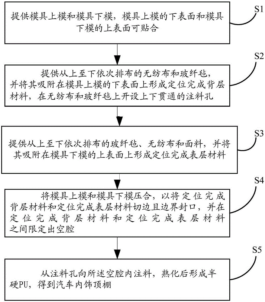
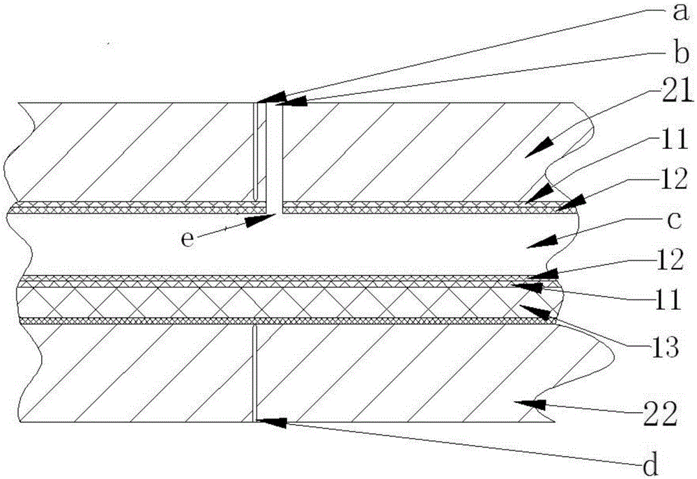
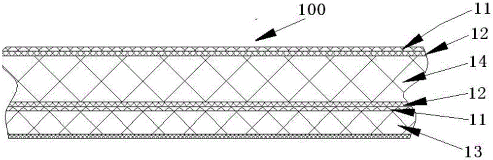
[0029] Embodiments of the present invention are described in detail below, examples of which are shown in the drawings, wherein the same or similar reference numerals designate the same or similar elements or elements having the same or similar functions throughout. The embodiments described below by referring to the figures are exemplary and are intended to explain the present invention and should not be construed as limiting the present invention.

[0030] In describing the present invention, it should be understood that the terms "center", "longitudinal", "transverse", "length", "width", "thickness", "upper", "lower", "front", " Back", "Left", "Right", "Vertical", "Horizontal", "Top", "Bottom", "Inner", "Outer", "Axial", "Radial", "Circumferential", etc. The indicated orientation or positional relationship is based on the orientation or positional relationship shown in the drawings, and is only for the convenience of describing the present invention and simplifying the desc...


PUM

PropertyMeasurementUnit
thicknessaaaaaaaaaa
Basis weightaaaaaaaaaa
thicknessaaaaaaaaaa

Abstract

The invention discloses a manufacturing method for the interior ceiling of an automobile. The method comprises the following steps: S1, providing an upper die and a lower die of a die, wherein the upper die and the lower die of the die fit each other; S2, providing a non-woven fabric and a glass fiber mat which are successively arranged from top to bottom, allowing the non-woven fabric and the glass fiber mat to be absorbed on the lower surface of the upper die to complete positioning so as to form a back material and perforating a material injection hole in the back layer which has undergone positioning; S3, providing a glass fiber mat, a non-woven fabric and a fabric which are successively arranged from top to bottom and allowing the glass fiber mat, the non-woven fabric and the fabric to be absorbed on the upper surface of the lower die to complete positioning so as to form a surface material; S4, pressing the upper die and the lower die together so as to trim the back layer having undergone positioning and the surface layer having undergone positioning and to seal boundaries and defining a cavity between the back layer having undergone positioning and the surface layer having undergone positioning; and S5, injecting a material from the material injection hole into the cavity and carrying out curing so as to form semi-hard PU, thereby obtaining the interior ceiling of the automobile. With the manufacturing method for the interior ceiling of the automobile disclosed in the embodiments of the invention, production procedures are reduced.

Description

technical field [0001] The invention relates to the technical field of automobile manufacturing, and more particularly, relates to a method for manufacturing an automobile interior ceiling. Background technique [0002] The production of automotive interior molding ceilings at home and abroad is mostly composed of non-woven fabrics, glass fiber felts, semi-rigid polyurethane foam sheets, glass fiber felts, non-woven fabrics, fabric layers and other multi-layer materials. After foaming, slicing, rolling, Multiple processes such as molding, shaping, glue spraying, composite fabrics, water cutting or punching, hemming, and bonding accessories are completed. [0003] After cutting the periphery and installation holes of the automotive interior molding ceiling, glass fiber exposure and fabric burrs will inevitably appear. For the required boundary parts, fabric wrapping needs to be performed. At the same time, the sheet molding production process adopted for the ceiling of the a...

Claims


Application Information

Patent Timeline
Patent Type & Authority Patents(China)
IPC IPC(8): B32B37/15B60R13/02
Inventor 徐素冲刘胜军薛风王东亮邢倩倩陈明明王江平赵帅
Owner GREAT WALL MOTOR CO LTD
Why Eureka
Try Eureka