A Stress Detection Method for Bolt Joints of Machine Tools
A stress detection and connection technology, applied in the direction of measuring force, measuring device, instrument, etc., can solve the problems of harsh test conditions, complex process and narrow application range.
- Summary
- Abstract
- Description
- Claims
- Application Information
AI Technical Summary
Problems solved by technology
Method used
Image
Examples
Embodiment 1
[0058] S1: Equipment preparation.
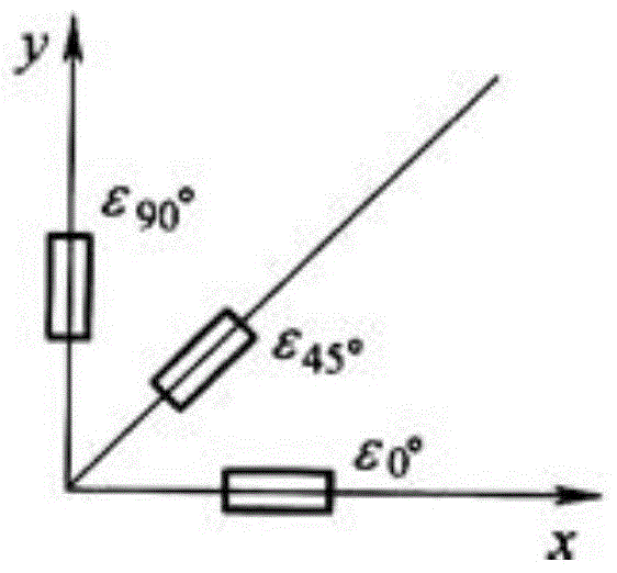
[0059] Prepare the following equipment: BE120-2BC three-way strain gauge, DH3816N static strain tester, temperature compensation block, notebook computer, 502 glue, electric soldering iron, solder, rosin, absolute alcohol, stainless steel tweezers, absorbent cotton, coarse sandpaper, metallographic Sandpaper, shielded wire, steel ruler, scribing needle, torque wrench, the bed and column of the μ2000 / 400H horizontal machining center produced by Beijing Gongyan Precision Machinery Co., Ltd., 26 M16 bolts, and the column is assembled to the bed by bolts Body. Among them, the material of the temperature compensation block is the same as the material of the column connected by the bolt, and both are HT150 (ie gray iron 150). The schematic diagram of the plane structure of the BE120-2BC three-way strain rosette is as follows figure 1 As shown, the resistors are respectively arranged along the directions with the angles of 0°, 45°, and 90° with respe...
Embodiment 2
[0084] This embodiment is the same as embodiment 1, except that:
[0085] In S2, use absorbent cotton to clean the test surface, use absorbent cotton balls dipped in acetone to clean the surface of the patch to remove dirt, and replace the absorbent cotton balls repeatedly until there is no stain on the surface;
[0086] In S2, the short-term insulation resistance of the joint between the strain rosette and the machine tool and the joint between the strain rosette and the column is detected. Since the test time is 6 days, the resistance of the test is greater than 20MΩ.
[0087] In S4, before testing, the static strain tester is energized for 15 minutes, preheated, and then the static strain tester is balanced.
Embodiment 3
[0089] This embodiment is the same as embodiment 1, except that:
[0090] In S4, before testing, the static strain tester is energized for 20 minutes, preheated, and then the static strain tester is balanced.
[0091] Figure 5 with Image 6 They are respectively the principal stress curve diagram detected at the measuring point on the column and the principal stress curve diagram obtained at the measuring point on the bed in the embodiment of the present invention. This is the test result obtained in Example 3 of the present invention. It can be seen from the maximum principal stress curve of the bed and the column that different bolt assembly processes have a great influence on the stress field distribution of the bed column connection. In the second method of assembly process, the stress field caused by the bolt connection assembly The distribution is relatively uniform, and the fluctuations between the measurement points are not as great as the method. In comparison, the meth...
PUM
| Property | Measurement | Unit |
|---|---|---|
| electrical resistance | aaaaa | aaaaa |
| electrical resistance | aaaaa | aaaaa |
Abstract
Description
Claims
Application Information
 - R&D
- Intellectual Property
- Life Sciences
- Materials
- Tech Scout
- Unparalleled Data Quality
- Higher Quality Content
- 60% Fewer Hallucinations
Browse by: Latest US Patents, China's latest patents, Technical Efficacy Thesaurus, Application Domain, Technology Topic, Popular Technical Reports.
© 2025 PatSnap. All rights reserved.Legal|Privacy policy|Modern Slavery Act Transparency Statement|Sitemap|About US| Contact US: help@patsnap.com


