Flue gas waste heat thermoelectric recovery device

A flue gas waste heat and recovery device technology, which is applied in the direction of electrical components, indirect heat exchangers, heat exchanger types, etc., can solve the problems of low recovery efficiency of thermoelectric power generation devices, low energy recovery utilization rate, and insufficient use of waste heat, etc. , to achieve the effect of small footprint, easy modification and easy installation

Active Publication Date: 2014-11-26
BAOSHAN IRON & STEEL CO LTD +1
View PDF5 Cites 16 Cited by
  • Summary
  • Abstract
  • Description
  • Claims
  • Application Information

AI Technical Summary

Problems solved by technology

Due to the limitation of the thermal conductivity of semiconductor materials, the temperature of the flue gas cannot be completely reduced after the thermoelectric power generation, and there is a situation that the wast

Method used


Image

  • Flue gas waste heat thermoelectric recovery device
  • Flue gas waste heat thermoelectric recovery device
  • Flue gas waste heat thermoelectric recovery device

Examples


Embodiment Construction

[0044] In the following, the flue gas waste heat thermoelectric recovery device according to the present invention will be further described in detail according to the specific embodiments and the accompanying drawings, but this description does not constitute a limitation of the present invention.

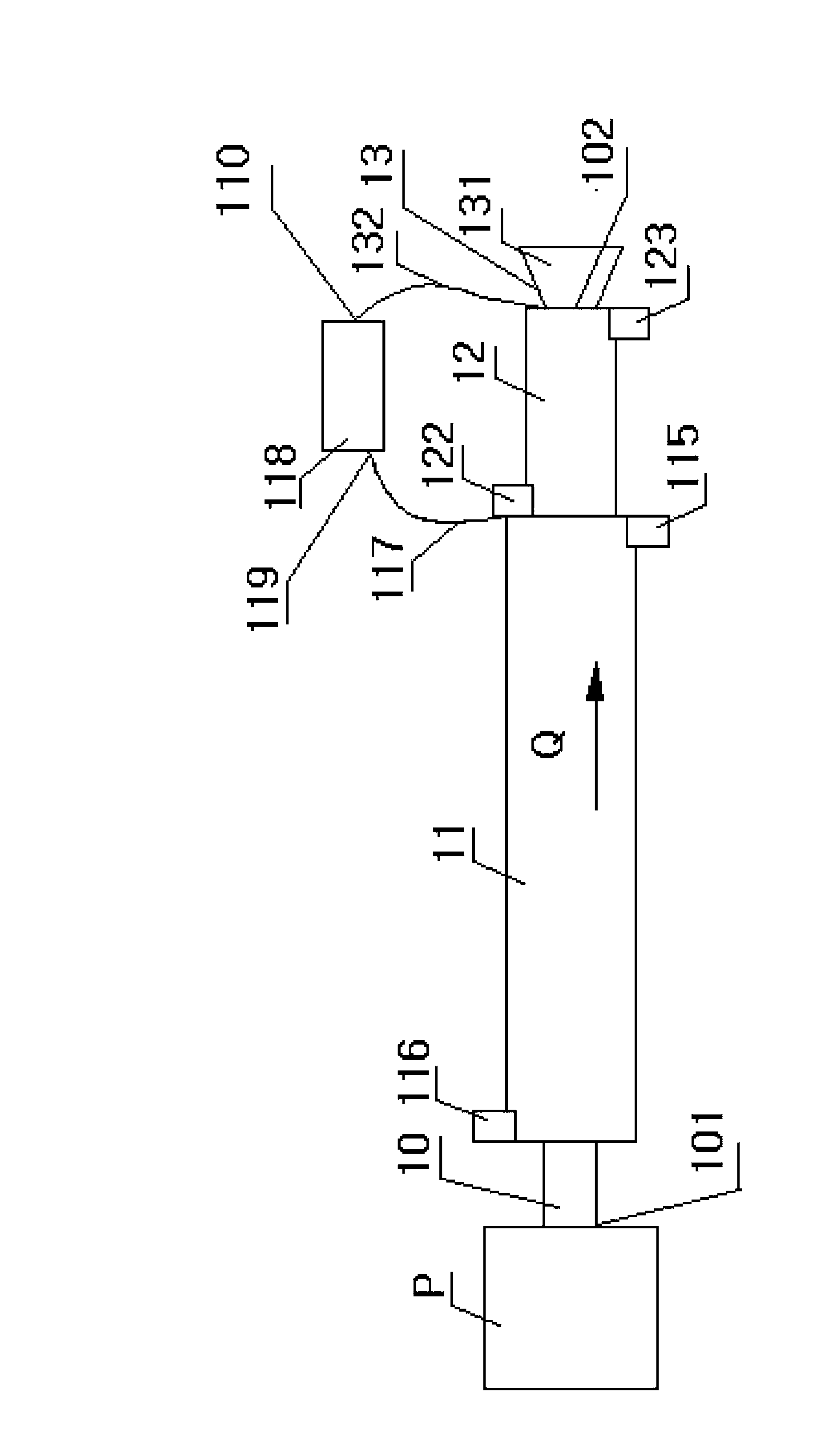
[0045] Such as figure 1 As shown, in this embodiment, the inlet 101 of the flue gas pipeline 10 is docked with the hot flue gas source P, the flue gas flows in the flue gas pipeline 10, and its flow direction is Q, and thermoelectric power generation is arranged sequentially along the flue gas flow direction. Section 11, hot water section 12 and air induction section 13, wherein the thermoelectric power generation section 11 and the hot water section 12 are both sleeved outside the flue gas pipe 10, and the air induction section 13 is arranged at the outlet 102 of the flue gas pipe 10.

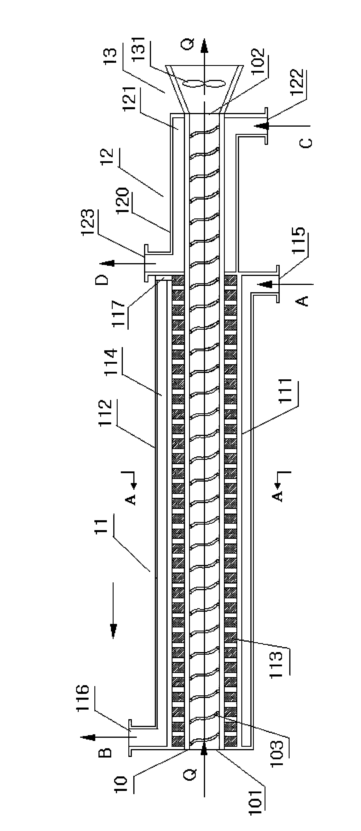
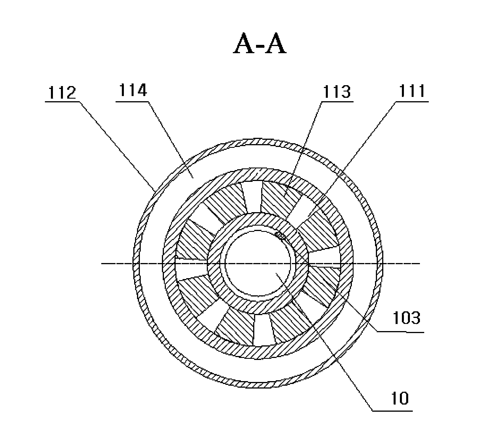
[0046] Such as figure 2 As shown, the inner wall of the flue gas duct 10 is provided with in...


PUM


Abstract

The invention discloses a flue gas waste heat thermoelectric recovery device which is arranged on a flue gas pipeline. The inner wall of the flue gas pipeline is provided with fins arranged along the overall length of the flue gas pipeline in the axial direction. The device comprises a temperature difference power generation section and a hot water section which are sequentially arranged in the flowing direction of the flue gas, wherein the temperature difference power generation section comprises a first pipe body which sleeves the flue gas pipeline. The first pipe body has a cold end of the temperature difference power generation section and a hot end of the temperature difference power generation section; and power generation modules are arranged between the first pipe body and the flue gas pipeline, wherein each power generation module closely attaches to the inner wall of the pipe body and the outer wall of the flue gas pipeline. The temperature difference power generation section also comprises a second pipe body which sleeves the first pipe body to form a cooling water annular pipeline, wherein the cooling water annular pipeline has a cooling water outlet and a cooling water inlet. The hot water section comprises a third pipe body which sleeves the flue gas pipeline to form a hot water annular pipeline, wherein the hot water annular pipeline has a hot water outlet and a hot water inlet, so that full recovery of the flue gas waste heat is realized.

Description

technical field [0001] The invention relates to a heat exchange assembly, in particular to a heat exchange assembly used for pipe fittings. Background technique [0002] At present, the work of energy saving and emission reduction is being promoted in an all-round way in the whole society, and a variety of energy saving and energy recovery methods have emerged accordingly. At present, my country's energy utilization rate is still at a low level, and waste heat recovery technology still has great development space and potential, so that a large amount of industrial waste heat / waste heat resources have not been effectively recycled due to the constraints of existing technologies. Taking the iron and steel industry as an example, the waste heat recovery rate of flue gas discharged from various furnaces in my country's iron and steel industry is only about 30%, which is far below the level of developed countries. Discharging all kinds of medium and high temperature flue gas dir...

Claims


Application Information

Patent Timeline
IPC IPC(8): H02N11/00F28D7/10
Inventor 张颖王加龙殷玫婕曹先常朱亚军陈忠平吴静怡
Owner BAOSHAN IRON & STEEL CO LTD
Why Eureka
Try Eureka