Electromagnetic clamping mechanism and linear driving device and combination with same

A clamping device and linear drive technology, applied in the direction of generators/motors, electrical components, etc., can solve the problems of small deformation of the clamp, loss of clamping function, and impossibility of realization, etc., to achieve sensitive motion control, fewer components, The effect of simple structure

Active Publication Date: 2014-11-26
杨斌堂
View PDF4 Cites 41 Cited by
  • Summary
  • Abstract
  • Description
  • Claims
  • Application Information

AI Technical Summary

Problems solved by technology

The piezoelectric clamping mechanism adopted by this kind of motor uses brittle piezoelectric materials, and its anti-extrusion ability is limited. Excessive clamping and pressure will crush the piezoelectric material, resulting in the loss of clamping function, and its The performanc...

Method used


Image

  • Electromagnetic clamping mechanism and linear driving device and combination with same
  • Electromagnetic clamping mechanism and linear driving device and combination with same
  • Electromagnetic clamping mechanism and linear driving device and combination with same

Examples


Embodiment 1

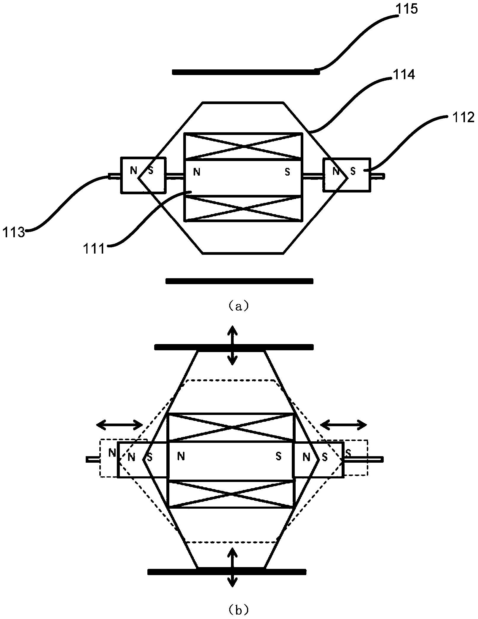
[0071] This embodiment provides the electromagnetic clamping mechanism of the first structure, including an electromagnet, a permanent magnet and a deformation body, the magnetic poles of the permanent magnets are in direct contact with or close to the magnetic poles of the electromagnet to form a control magnetic circuit, and the deformation body It is rigidly connected with the permanent magnet; the permanent magnet moves relative to the electromagnet under the drive of the magnetic field of the control magnetic circuit, and drives the deformable body to deform, thereby realizing clamp locking and release.

[0072] Specifically:

[0073] There are two permanent magnets 112, which are respectively arranged on the magnetic link of the electromagnet 111. A control magnetic circuit is formed between the two permanent magnets 112 and the electromagnet 111 located in the middle position, and the deformation body 113 is rigidly connected with the permanent magnet 112. In this embod...

Embodiment 2

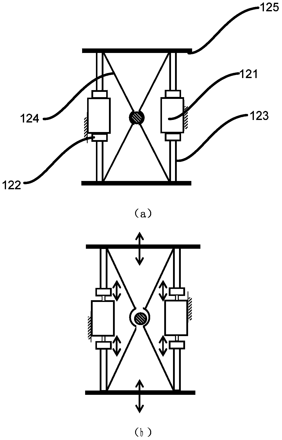
[0080] This embodiment provides the electromagnetic clamping mechanism of the second structure, which has the same working principle as the electromagnetic clamping mechanism provided in Embodiment 1. The difference from Embodiment 1 is that there are two deformation bodies Correspondingly, there are two sets of permanent magnet electromagnetic combinations for driving the two shrapnels for the pre-tensioned shrapnel with matching bayonet.

[0081] Specifically:

[0082] Each group of permanent magnet electromagnetic combination all comprises: two permanent magnets 122 are arranged on the magnetic link of electromagnet 121 respectively, and form control magnetic circuit with electromagnet 121, further, between electromagnet 121 and permanent magnet 122 It is also coaxially arranged on the moving shaft 124; the outer ends of the two permanent magnets 122 are respectively provided with rigid material bodies, and the two ends of the deformable body 123 are fixedly connected with ...

Embodiment 3

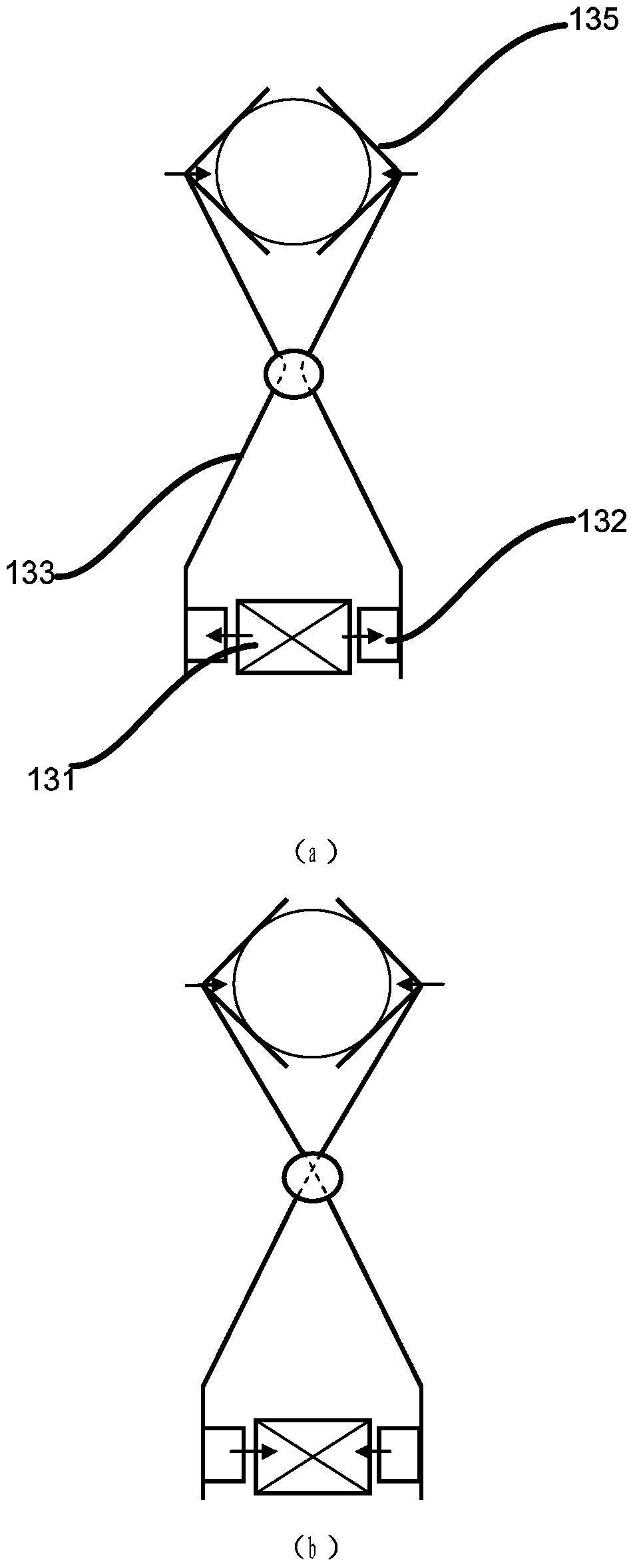
[0087] This embodiment provides the electromagnetic clamping mechanism of the third structure, and the electromagnetic clamping mechanism has the same working principle as that of Embodiment 1. The difference from Embodiment 1 is that the deformed body used in this embodiment is a hand pliers Structural variants.

[0088] Such as image 3 Shown in (a), it is the deformed body 133 of the hand pliers structure of the first structure. The two V-shaped elastic bodies that constitute the deformed body 133 of the hand pliers mechanism are symmetrically arranged and connected axially. When the permanent magnet 132 is opposite to the electromagnet 131 When moving away, push the lower end of the pliers structure deformation body 133 away. Correspondingly, the upper end of the hand pliers structure deformation body 133 approaches and finally locks under the driving force to realize the clamping and locking state.

[0089] Such as image 3 As shown in (b), it is the deformed body of th...


PUM


Abstract

The invention provides an electromagnetic clamping mechanism which comprises an electromagnet, a permanent magnet and a deformable body. The permanent magnet is arranged on a magnetic link of the electromagnet, a control magnetic circuit is formed between the permanent magnet and the electromagnet, the permanent magnet moves relative to the electromagnet under the drive of the magnetic field of the control magnetic circuit, the deformable body is driven to deform, and then clamping locking and releasing are achieved. The invention further provides a linear driving device and combination with the electromagnetic clamping mechanism. According to the electromagnetic clamping mechanism and the linear driving device and combination with the electromagnetic clamping mechanism, due to the fact that magnetic poles of the permanent magnet and the electromagnet make contact with each other or are close to each other, the functions of large driving force, large displacement, high-precision driving and power off clamping keeping are formed, existing electric and magnetostrictive drive material application equipment and instruments are improved, and the electromagnetic clamping mechanism and the linear driving device and combination with the electromagnetic clamping mechanism can be widely applied in the field of drivers (actuators), brakes, sensors, motors, vibration and control equipment, robots, precision manufacturing, biomedical engineering and the like.

Description

technical field [0001] The invention relates to the technical field of electromagnetic motors, in particular to an electromagnetic clamping mechanism, a linear drive device and a combination thereof. Background technique [0002] In recent years, electric and magnetostrictive drive technologies have developed rapidly, resulting in smart materials such as giant magnetostrictive materials, electric ceramics, and magnetostrictive shape memory alloys. These smart materials have the advantages of high energy density, high output power, and precise stretching and deformation. Therefore, high-performance drives and linear motors can be developed based on these smart materials. However, the linear motors developed based on smart materials, especially for inchworm motion linear motors, do not have a clamping mechanism with matching performance, so that the large output stress performance of smart materials cannot be fully utilized, so that this type of motor cannot be used. Ultra-la...

Claims


Application Information

Patent Timeline
IPC IPC(8): H02N11/00
Inventor 杨斌堂
Owner 杨斌堂
Why Eureka
Try Eureka