
Carrier substrate and manufacturing method thereof

A technology for carrying a substrate and a manufacturing method, which is applied in the manufacturing of multi-layer circuits, printed circuits connected with non-printed electrical components, and electrical connection of printed components, etc. and wiring, oxidation and other problems, to maintain electrical performance, avoid oxidation, and improve bonding reliability.

Active Publication Date: 2017-05-24
UNIMICRON TECH CORP
View PDF5 Cites 0 Cited by
  • Summary
  • Abstract
  • Description
  • Claims
  • Application Information

AI Technical Summary

Problems solved by technology

[0003] However, the connection pads and traces on the existing carrier substrate are on the same level, and the opening of the solder resist layer will expose the connection pads and traces in the pre-connection area at the same time
Therefore, in addition to the above-mentioned configuration, it is easy to cause the wiring to oxidize and affect the electrical performance, and the user cannot easily distinguish the connection pad from the wiring, so that it is impossible to accurately connect the component directly to the connection pad.

Method used


Image

  • Carrier substrate and manufacturing method thereof
  • Carrier substrate and manufacturing method thereof
  • Carrier substrate and manufacturing method thereof

Examples


Embodiment Construction

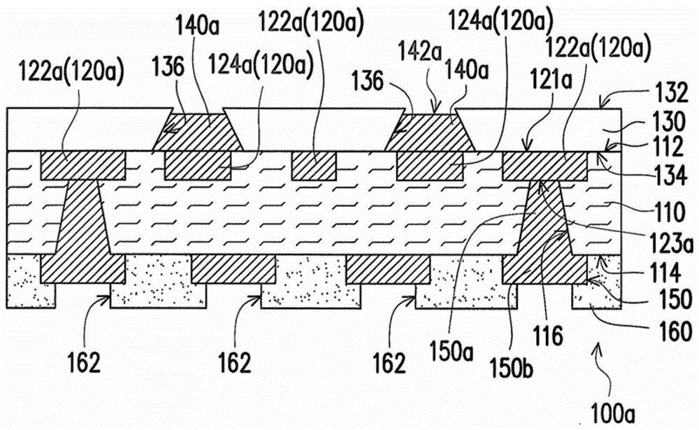
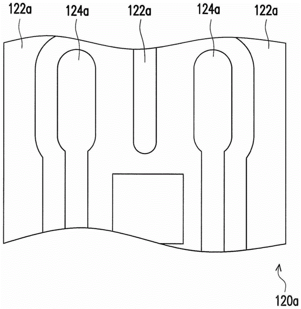
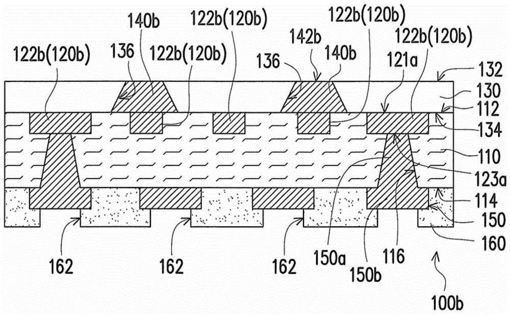
[0069] Figure 1A A schematic cross-sectional view of a carrier substrate according to an embodiment of the present invention is shown. Figure 1B shown as Figure 1A A schematic top view of the circuit layer. Please refer to Figure 1A , in this embodiment, the carrier substrate 100a includes a dielectric layer 110 , a first circuit layer 120a , an insulating layer 130 , a plurality of conductive blocks 140a and a first conductive structure 150 . In detail, the dielectric layer 110 has two opposite surfaces 112, 114 and a plurality of blind holes 116 ( Figure 1A Two are schematically shown in ). The first wiring layer 120a is embedded in the surface 112 of the dielectric layer 110 and has two opposite surfaces 121a, 123a, wherein the surface 121a is exposed on the surface 112 of the dielectric layer 110 . The blind hole 116 extends from the surface 114 to the first wiring layer 120a and exposes a portion of the surface 123a of the first wiring layer 120a. The insulating la...


PUM


Abstract

The invention discloses a carrier substrate and a manufacturing method thereof. The carrier substrate includes a dielectric layer, a first circuit layer, an insulating layer, a plurality of conductive blocks and a first conductive structure. The dielectric layer has a first surface, a second surface and a plurality of blind holes. The first circuit layer is buried in the first surface, and the blind hole extends from the second surface to the first circuit layer. The insulating layer is disposed on the first surface and has a third surface, a fourth surface and a plurality of first openings. The first opening exposes the first circuit layer, and the diameter of each first opening gradually increases from the third surface toward the fourth surface. The conductive block fills the first opening and connects to the first circuit layer. The first conductive structure includes a plurality of conductive holes filled with blind holes and a second circuit layer disposed on a portion of the second surface.

Description

technical field [0001] The invention relates to a substrate and a manufacturing method thereof, and in particular to a carrier substrate suitable for carrying components and a manufacturing method thereof. Background technique [0002] In recent years, with the rapid development of electronic technology and the emergence of high-tech electronic industries, electronic products with more humanization and better functions are constantly being introduced, and are designed towards the trend of light, thin, short and small. In these electronic products, a carrier substrate is usually arranged. In addition to having conductive circuits, the carrier substrate can also carry components such as capacitors, inductors, resistors, IC chips or packages as a data processing unit of the electronic products. [0003] However, the connection pads and the traces on the conventional carrier substrate are on the same level, and the opening of the solder resist layer will simultaneously expose th...

Claims


Application Information

Patent Timeline
Patent Type & Authority Patents(China)
IPC IPC(8): H05K1/02H05K1/11H05K1/18H05K3/32H05K3/46
Inventor 林俊廷
Owner UNIMICRON TECH CORP
Learn More