Efficient electrostatic-dielectrophoresis deduster

A technology of dielectrophoresis and electrostatic dust removal, used in electrostatic effect separation, chemical instruments and methods, solid separation, etc., can solve the problems of high power consumption, limited capture capacity, hidden dangers, etc., and achieve low energy consumption and operating costs. Low, low pressure loss effect

Inactive Publication Date: 2014-12-03
CHENGDU DAIDAIJI PROSPECTIVE TECH
View PDF10 Cites 3 Cited by
  • Summary
  • Abstract
  • Description
  • Claims
  • Application Information

AI Technical Summary

Problems solved by technology

[0003] At present, the electrostatic precipitator widely used in industry has been widely used because of its large amount of flue gas treatment and small pressure loss of the precipitator body. However, the use of the electrostatic precipitator also has its limitations. It is easily affected by many factors such as the physical and chemical properties of flue gas and dust (such as flue gas temperature, flue gas humidity, flue gas velocity, dust particle size distribution, dust viscosity, sulfur content, etc.), especially when dealing with high specific resistance dust And fine dust (especially dust below 10um, the electrostatic precipitator has limited ability to collect fine dust, because fine dust is difficult to charge, and the electrode vibrates to generate secondary dust, so that the captured particles escape with the airflow), Electrostatic precipitator shows its incompatibility
[0004] The electrostatic precipitator is not effective in removing particles below 10um, especially the particles that can enter the lungs (with a particle diameter of 2.5um or less). In the atmosphere, it has buried hidden dangers for the health and safety of the public

Method used


Image

  • Efficient electrostatic-dielectrophoresis deduster
  • Efficient electrostatic-dielectrophoresis deduster
  • Efficient electrostatic-dielectrophoresis deduster

Examples


Embodiment Construction

[0049] Embodiments of the present invention are described in detail below, examples of which are shown in the drawings, wherein the same or similar reference numerals designate the same or similar elements or elements having the same or similar functions throughout. The embodiments described below by referring to the figures are exemplary only for explaining the present invention and should not be construed as limiting the present invention.

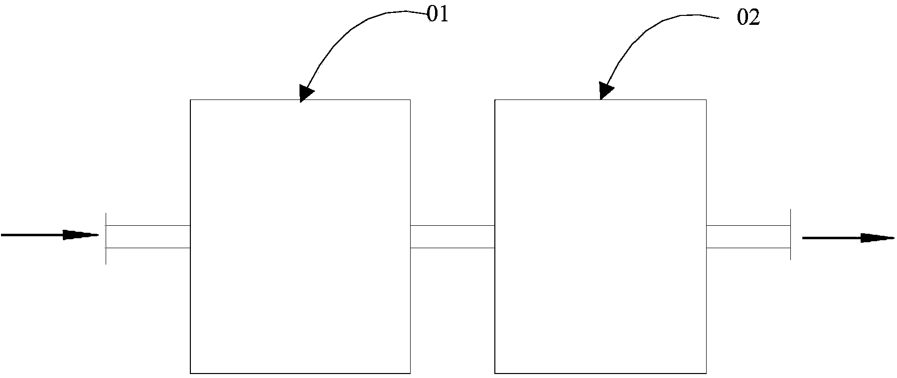
[0050] The invention provides a high-efficiency electrostatic-dielectrophoretic dust collector, such as figure 1 As shown, it includes an electrostatic precipitator 01 and a dielectrophoretic filter 02. Among them, the electrostatic precipitator has an air inlet and an air outlet, and the electrostatic precipitator is also equipped with a corona electrode, a dust collecting plate, a high voltage power supply device, an ash hopper and an ash removal device. In this embodiment, the electrostatic precipitator can adopt the structure of the...


PUM


Abstract

The invention provides an efficient electrostatic-dielectrophoresis deduster. The efficient electrostatic-dielectrophoresis deduster comprises an electrostatic dedusting part and a dielectrophoresis filtering part, wherein the dielectrophoresis filtering part consists of DEP purifying treatment units, each DEP purifying treatment unit comprises M DEP purifying electrode plates, the arrangement direction of the M DEP purifying electrode plates is parallel or approximately parallel to the gas inlet direction, each DEP purifying electrode plate comprises a DEP electrode, and each DEP electrode comprises an anode and a cathode which are arranged oppositely and is used for trapping particulate matters in exhaust gas of the electrostatic dedusting part by a dielectrophoresis force. According to the efficient electrostatic-dielectrophoresis deduster, large particulate dust in inlet gas is filtered by the electrostatic dedusting part, and small particles, particularly respirable dust, can be filtered by the dielectrophoresis filtering part, so that the full-range and comprehensive removal of dust particles is realized. Dielectrophoresis of the dielectrophoresis filtering part is far away from filtered dust, so that the energy consumption is low, the pressure loss is low, and the operating cost is low.

Description

technical field [0001] The invention relates to the technical field of material purification treatment, in particular to a high-efficiency electrostatic-dielectrophoresis dust collector using dielectrophoresis dust removal technology. Background technique [0002] PM2.5 is particles smaller than 2.5 microns, also known as particles that can enter the lungs, which can enter the alveoli and even the blood system of the human body, directly causing cardiovascular diseases and other diseases. PM2.5 has a large specific surface area and is usually enriched with various heavy metal elements, such as As, Se, Pb, Cr, etc., as well as organic pollutants such as PAHs, PCDD / Fs, VOCs, etc. These are mostly carcinogens and genotoxic mutagenesis Material hazards are extremely high. Known health effects of PM2.5 include increased mortality in patients with severe and chronic diseases. It can worsen diseases of respiratory system and heart system, change lung function and structure, and c...

Claims


Application Information

Patent Timeline
Patent Type & Authority Applications(China)
IPC IPC(8): B03C3/017
Inventor 阮海生
Owner CHENGDU DAIDAIJI PROSPECTIVE TECH
Why Eureka
Try Eureka