
Three-dimensional high-directivity infrared aircraft landing guide system

An infrared light and high-pointing technology, applied in the field of aerospace engineering, can solve problems such as poor penetration rate, influence of indication accuracy, and limited working range, so as to increase the navigable distance and reduce waste

Active Publication Date: 2014-12-03
UNIV OF ELECTRONICS SCI & TECH OF CHINA
View PDF4 Cites 21 Cited by
  • Summary
  • Abstract
  • Description
  • Claims
  • Application Information

AI Technical Summary

Problems solved by technology

[0003] There are still some problems in the existing ILS: a single ILS cannot meet the requirements of category III precision approach and landing in terms of indication accuracy; the number of ILS channels is small (40), which cannot meet the requirements of the increase in air traffic in the future on the number of airstrips; Requirements, will affect the take-off and landing time of the aircraft; the ILS antenna coverage beam is susceptible to instantaneous interference from other passing aircraft; the approach sector coverage is narrow, and can only approach along the centerline, making it difficult for the pilot to make decisions and poor maneuverability; The frequency is quite crowded in the meter wave band, which is easily interfered by adjacent stations, which will affect the accuracy of the indication; the requirements for the terrain around the airport are strict, and it is easily affected by meteorological conditions (such as snow reflection)
However, due to the near-infrared band of the LED, the transmittance is poor, and the LED is a high-divergence light source, most of the light is diverged to directions that are not related to navigation, so that the working range of this method is relatively limited, and its energy consumption The efficiency is also relatively low

Method used


Image

  • Three-dimensional high-directivity infrared aircraft landing guide system

Examples


Embodiment Construction

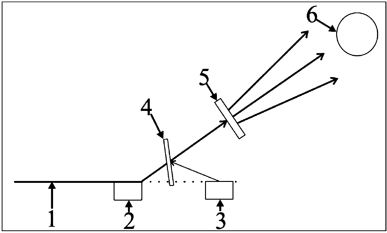
[0016] The three-dimensional high-directivity infrared light aircraft landing guidance system includes an infrared laser source with low divergence characteristics emitted along the optimal landing angle, a light source that emits a visible calibration beam, an optical device that allows the infrared laser and the visible calibration beam to converge together, and allows the laser An optical system that generates optical images of directional radiation, an infrared light detection system configured on an aircraft, and an optical image recognition analysis display system. By letting the laser generate an optical image of directional radiation, it can provide the pilot with the information needed for the aircraft to land.

[0017] The infrared laser source is placed below the best landing point on the runway and emits in the direction of the best landing angle. The emitted infrared light wavelength is within the range of 3-5um or 8-12um, and it is a polarized light source . The...


PUM

PropertyMeasurementUnit
Wavelengthaaaaaaaaaa

Abstract

The invention discloses a three-dimensional high-directivity infrared aircraft landing guide system. The three-dimensional high-directivity aircraft landing guide system is mainly characterized in that optical images with required aircraft landing information are generated in air by the aid of high-penetration and high-directivity infrared laser light via an optical system and can cover large flight intervals, so that aircrafts can detect the optical images in the large flight intervals, and the aircrafts or aircraft pilots can be guided via the information provided by the optical images to find the optimal landing routes, and the aircrafts can be smoothly landed. The three-dimensional high-directivity infrared aircraft landing guide system has the advantages that the navigation information is pertinently transmitted only in specific directions by the aid of the high-directivity infrared laser light, accordingly, energy wastage can be reduced, the navigable distances can be increased, and the anti-interference performance can be improved.

Description

technical field [0001] The invention relates to a three-dimensional high-directivity infrared light aircraft landing guidance system, which belongs to the field of aerospace engineering. Background technique [0002] The landing system is to enable the pilot to accurately control the aircraft to enter the runway under various complex weather conditions according to the instructions of the navigation instruments on the aircraft or the guidance of ground radio equipment (such as radar, radio direction station, etc.), so as to help the aircraft land safely. system. The airport blind landing is divided into three levels: Type I requires the runway visibility to be greater than 800 meters; Type II requires the runway visibility to be no less than 350 meters; Type III requires the runway visibility to be no less than 210 meters. The two main landing systems are the ILS instrument landing system and the MLS microwave landing system. ILS is the standard landing equipment confirmed...

Claims


Application Information

Patent Timeline
IPC IPC(8): B64F1/18G01C21/00
CPCB64D45/08B64F1/18G01S5/16G01S7/499
Inventor 段兆云陈敏林宗欣陈红胜
Owner UNIV OF ELECTRONICS SCI & TECH OF CHINA
Learn More