
Ultrasonic-vibration activation-assisted sintering box-type resistance furnace

A box-type resistance furnace, ultrasonic vibration technology, applied in furnaces, crucible furnaces, furnace types, etc., can solve problems such as unseen applications, and achieve the effects of wide adaptability, low porosity, and uniform distribution

Inactive Publication Date: 2014-12-03
CHONGQING UNIVERSITY OF SCIENCE AND TECHNOLOGY
View PDF8 Cites 11 Cited by
  • Summary
  • Abstract
  • Description
  • Claims
  • Application Information

AI Technical Summary

Problems solved by technology

Ultrasound has unique mechanical effects, thermal effects and cavitation effects. The use of ultrasonic technology to activate assisted sintering can refine the structure of sintered products and reduce the porosity of sintered products, but it has not been used in the sintering process of materials so far.

Method used


Image

  • Ultrasonic-vibration activation-assisted sintering box-type resistance furnace
  • Ultrasonic-vibration activation-assisted sintering box-type resistance furnace

Examples


Embodiment 1

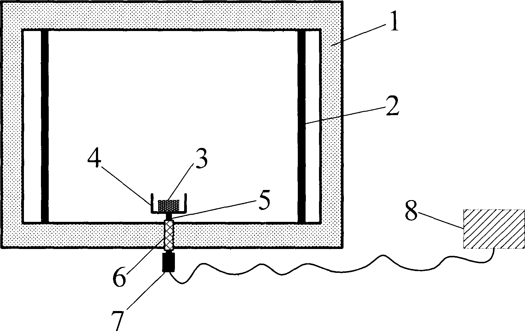
[0021] Such as figure 1 As shown in the front view schematic diagram of the bottom installation of the ultrasonic vibration activation auxiliary sintering resistance furnace ultrasonic device, the ultrasonic vibration activation auxiliary sintering resistance furnace ultrasonic device provided by the present invention is a bottom installation form, a hollow cylindrical annular alumina ceramic horn support frame 6 passes through the small hole at the bottom of the furnace shell 1, the alumina ceramic horn 5 passes through the horn support frame 6, and one end of the horn 5 in the furnace is connected to the alumina ceramic with a corresponding inner thread at the bottom through an external thread The crucible 4 is connected to an ultrasonic transducer 7 with a working frequency of 20 kHz by threading at one end outside the furnace of the horn 5 , and the ultrasonic transducer 7 is connected to the ultrasonic generator 8 through wires. Put the sample 3 to be fired into the cruci...

Embodiment 2

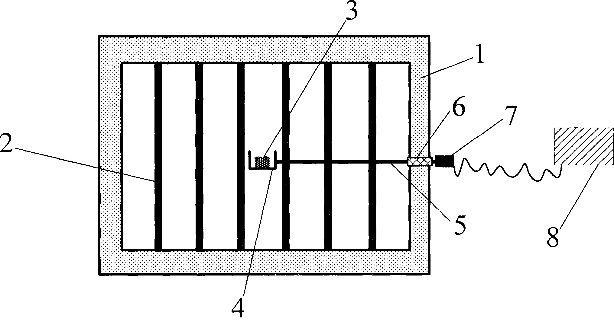
[0023] Such as figure 2 As shown in the side-view schematic diagram of the ultrasonic vibration activation auxiliary sintering box-type resistance furnace ultrasonic device, the ultrasonic vibration activation auxiliary sintering resistance furnace ultrasonic device provided by the present invention is in the form of side installation, and is supported by a hollow cylindrical annular high-temperature alloy steel horn The frame 6 passes through the small hole on the side of the furnace shell 1, the high-temperature alloy steel horn 5 passes through the horn support frame 6, and one end of the horn 5 in the furnace is connected to a high-temperature furnace with a corresponding internal thread on the side through an external thread. The alloy steel crucible 4 is connected to an ultrasonic transducer 7 with a working frequency of 40 kHz by threading at one end outside the hearth of the horn 5 , and the ultrasonic transducer 7 is connected to the ultrasonic generator 8 through wir...


PUM


Abstract

The invention provides an ultrasonic-vibration activation-assisted sintering box-type resistance furnace aiming at actual demands of research and development of new materials upon a sintering technology, inherent defects of the resistance furnace and the advantages of an ultrasonic technology. The ultrasonic-vibration activation-assisted sintering box-type resistance furnace comprises a furnace shell, a heating element, a furnace door, a crucible, an amplitude-change pole, an amplitude-change pole supporting frame, an ultrasonic generator and an ultrasonic transducer; ultrasonic power and loading time are controlled through the ultrasonic generator, electrical signals generated from the ultrasonic generator are converted into ultrasonic vibration through the ultrasonic transducer, the ultrasonic vibration transfers to-be-sintered samples through the amplitude-change pole and the crucible, the to-be-sintered samples are enabled to be in the ultrasonic vibration state during sintering, matter particulates of the to-be-sintered samples vibrate at a high speed under high temperature to promote crystal particulates of the to-be-sintered samples to evenly nucleate and grow up or evenly melt. By the arrangement, micro-structure of the massive sintering samples is evener and more compact, and powdery sintering samples can be more evenly dispersed.

Description

technical field [0001] The invention relates to a resistance sintering furnace, in particular to a box-type resistance sintering furnace which is activated by ultrasonic vibration to assist in sintering inorganic materials such as ceramics. Background technique [0002] Sintering is the core link in the preparation process of inorganic materials such as ceramics. During the sintering process, the material forms unique physical and chemical characteristics such as crystal structure, particle size, morphology, dislocations, and defects, so that the material has unique properties. Resistance heating sintering furnace has the advantages of simple structure, uniform furnace temperature, easy control, good heating quality, no smoke, no noise, etc. It is widely used in the research and development of new materials and small batch production in colleges and universities, research institutions and enterprises. Compared with the sintered products in industrial kilns such as roller ki...

Claims


Application Information

Patent Timeline
Patent Type & Authority Applications(China)
IPC IPC(8): F27B14/06F27B14/08C04B35/64
Inventor 邸永江贾碧邱杨施越
Owner CHONGQING UNIVERSITY OF SCIENCE AND TECHNOLOGY
Learn More