Unlock instant, AI-driven research and patent intelligence for your innovation.

Power module group of three-phase power electronic transformer

A power module group and electronic transformer technology, applied in the direction of reversible conversion equipment, etc., can solve the problems of power supply side, unadjustable power factor of the primary side, harmonic pollution of iron core magnetic saturation, etc., to achieve easy design, Improved utilization and reliability of power supply, easy modularization

Active Publication Date: 2014-12-03
STATE GRID CORP OF CHINA +1
View PDF7 Cites 6 Cited by
  • Summary
  • Abstract
  • Description
  • Claims
  • Application Information

AI Technical Summary

Problems solved by technology

[0004] 1. The volume and weight are large, and the insulating oil of the transformer pollutes the environment;
[0005] 2. The no-load loss is high, and the output voltage fluctuates with the load when it is loaded;
[0006] 3. When a fault occurs on the load side, the fault cannot be isolated and will affect the power supply side;
[0007] 4. When carrying a nonlinear load, the distorted current is coupled into the power grid through the transformer, which will cause pollution to the power grid;
[0008] 5. When the voltage on the power supply side is disturbed, it will be transmitted to the load side, resulting in an impact on sensitive loads;
[0010] 7. The ferromagnetic element is non-linear, which will cause a large excitation inrush current when it is put into the grid, and harmonic pollution will be generated when the iron core is magnetically saturated, resulting in distortion of the grid voltage and current, and increased vibration and noise
The disadvantage is that the controllability is not strong, sometimes it is difficult to contribute to the improvement of power quality, and the power factor of the primary side is not adjustable
However, since photovoltaic, wind power and other renewable energy sources and energy storage devices are usually connected to the DC system, the voltage is usually low, and the DC voltage values ​​are not necessarily equal, that is, multiple low-voltage DCs are required instead of one high-voltage DC
Therefore, the advantage of a high-voltage direct current generated by multiple MMC bridge arms cannot be fully utilized, and the disadvantages of the relatively large number of power electronic devices and capacitors used in this scheme have not been effectively offset

Method used


Image

  • Power module group of three-phase power electronic transformer
  • Power module group of three-phase power electronic transformer
  • Power module group of three-phase power electronic transformer

Examples


Embodiment 1

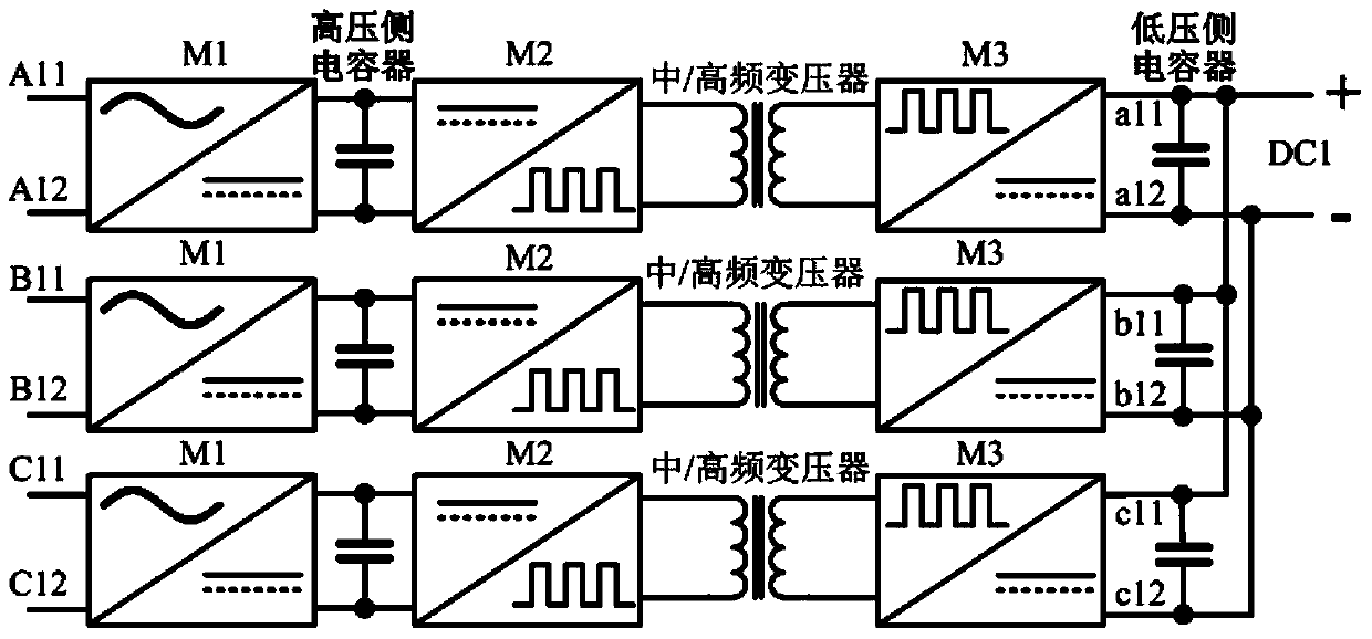
[0118] Embodiment 1, a three-phase power electronic transformer based on a power module unit M.

[0119] In this embodiment, when the number of AC side series connections of the first power module M1 is 3n, each phase uses 3n power module units of M structure to form a power module group, reducing the overall number of power modules and corresponding costs, where n is positive integer.

[0120] Such as Figure 7 as shown, Figure 7 It is a schematic diagram of Embodiment 1 of the three-phase power electronic transformer in this embodiment. For the required high-voltage AC level voltage, the calculated number of AC-side series connections corresponding to the first power module M1 is 3n, where n is a natural number. If the calculated number of AC side series connection corresponding to the first power module M1 is 3n+1 or 3n+2, as shown in the second and third embodiments below.

[0121] For each phase, there are 3n power modules M whose high-voltage AC sides are connected ...

Embodiment 2

[0124] Embodiment 2, a three-phase power electronic transformer based on the power module unit M and the power module unit M / 3.

[0125] If the AC side series connection number of the first power module M1 is 3n+1, and there is no separate DC output requirement, each phase uses 3n power module units with M structure and 1 power module unit with M / 3 structure to form the power The module group reduces the total number of power modules and the corresponding cost, n is a positive integer.

[0126] Such as Figure 8 as shown, Figure 8It is a schematic diagram of the second embodiment of the three-phase power electronic transformer in this embodiment. For the required high-voltage AC level voltage, the calculated number of AC-side series connections corresponding to the first power module M1 is 3n+1 (n is a positive integer).

[0127] In this embodiment, n is a natural number 1, that is, the number of the first power module M1 connected in series on the AC side is four. Theref...

Embodiment 3

[0130] Embodiment 3, a three-phase power electronic transformer based on the power module unit M and the power module unit M / 3.

[0131] If the number of AC side series connection of the first power module M1 is 3n+1 or 3n+2, and there is a requirement for DC output, each phase adopts the corresponding combination of M-structured power module units and M / 3-structured power module units to form a corresponding The power module group meets the corresponding DC output. At the same time, the corresponding combination of the power module unit of the M structure and the power module unit of the M / 3 structure constitutes the corresponding power module group to meet the corresponding AC output, so as to reduce the overall number of power modules And the corresponding cost, n is a positive integer.

[0132] Such as Figure 9 as shown, Figure 9 It is a schematic diagram of the third embodiment of the three-phase power electronic transformer in this embodiment. For the required high-...


PUM


Abstract

The invention provides a power module group of a three-phase power electronic transformer. The three-phase power electronic transformer comprises a high-voltage filter, the power module group, a fifth power module and a low-voltage filter. The power module group comprises power module units which are connected in series on the high-voltage side and connected in parallel on the low-voltage side. Each power module unit comprises a first power module, a high-voltage side capacitor, a second power module, a medium / high frequency transformer and a third power module, wherein the first power module, the high-voltage side capacitor, the second power module, the medium / high frequency transformer and the third power module are sequentially connected, and the third power module is connected with a low-voltage side capacitor in parallel. The power electronic transformer has the three-phase power automatic balance function, asymmetric loads on the low-voltage side can be well treated, and asymmetry on the low-voltage side can be naturally converted into symmetry on the high-voltage side through topological connection.

Description

technical field [0001] The invention relates to a device in the technical field of power electronic transformers, in particular to a power module group of a three-phase power electronic transformer. Background technique [0002] The concept of "active distribution network" and continuous practice can solve a series of technical problems brought about by the rapid development and accelerated application of distributed generation technology. The active distribution network aims to improve the active energy distribution ability and economic operation level of the distribution network, actively absorb renewable energy, improve the power supply reliability and power quality level of the distribution network, and make the distribution network more efficient and environmentally friendly. At the same time, the controllability of the distribution network is required to be higher. [0003] As the basic component equipment of the distribution network, the distribution transformer's op...

Claims


Application Information

Patent Timeline
IPC IPC(8): H02M7/72
Inventor 戴朝波
Owner STATE GRID CORP OF CHINA
Features
  • R&D
  • Intellectual Property
  • Life Sciences
  • Materials
  • Tech Scout
  • Unparalleled Data Quality
  • Higher Quality Content
  • 60% Fewer Hallucinations
Learn More