Film covering machine for film covering of ends of catalyst and film covering method of film covering machine

A coating machine and catalyst technology, applied in the field of automatic catalyst production equipment, can solve the problems of unguaranteed coating film quality, poor working environment for workers, corrosiveness, etc., achieve convenient coating, improve automation level, use and The effect of easy maintenance

Inactive Publication Date: 2014-12-10
BEIJING RES INST OF AUTOMATION FOR MACHINERY IND
View PDF6 Cites 40 Cited by
  • Summary
  • Abstract
  • Description
  • Claims
  • Application Information

AI Technical Summary

Problems solved by technology

The catalyst itself is corrosive, accompanied by harmful gases and dust. In the production process, if the film is manually covered on the end of the workpiece, not only the quality of the film cannot be guaranteed, but also the efficiency is low. The working environment of workers Relatively poor, long-term work in this environment will cause personal injury

Method used


Image

  • Film covering machine for film covering of ends of catalyst and film covering method of film covering machine
  • Film covering machine for film covering of ends of catalyst and film covering method of film covering machine
  • Film covering machine for film covering of ends of catalyst and film covering method of film covering machine

Examples


Embodiment Construction

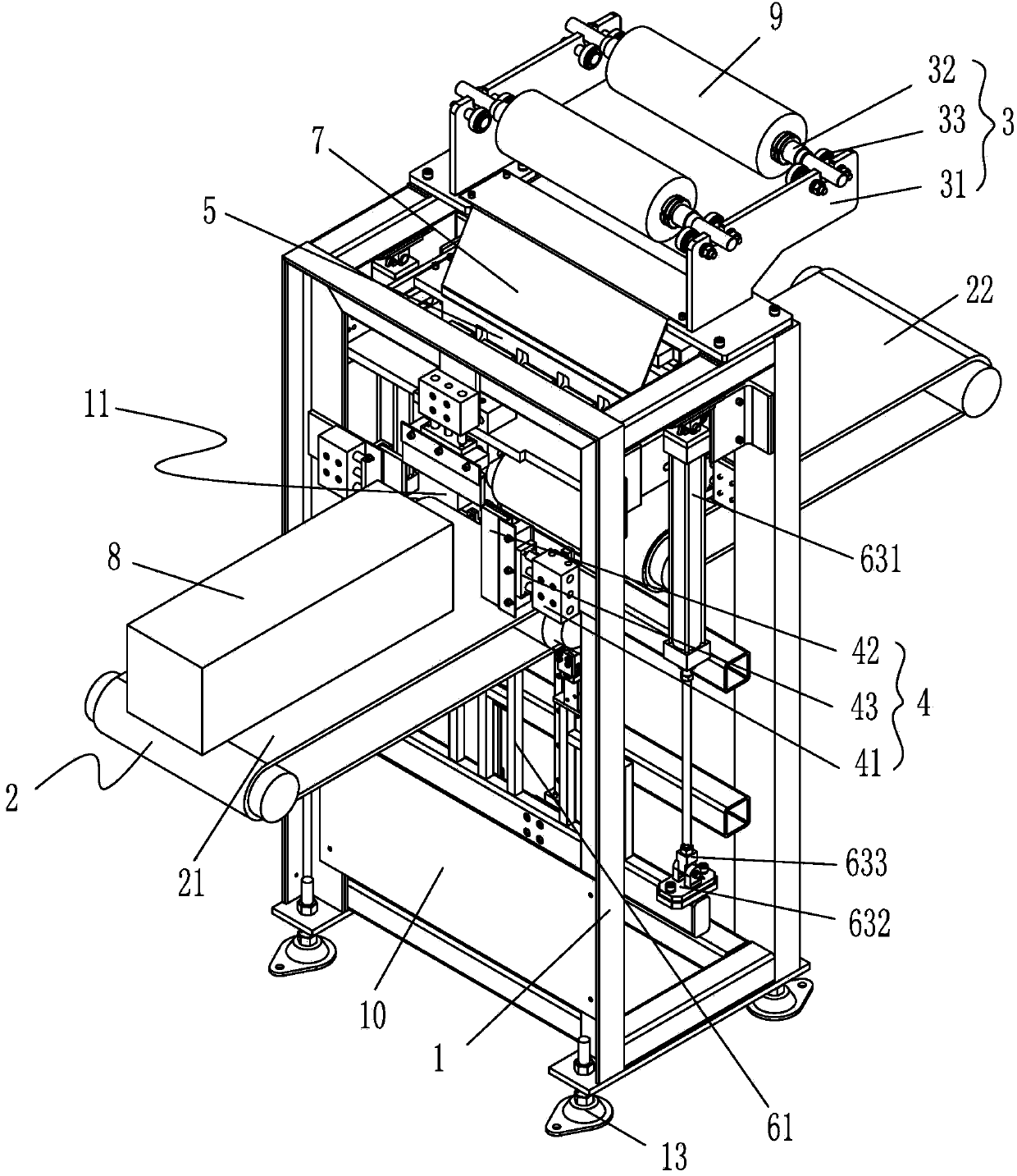
[0103] Below in conjunction with accompanying drawing, structural principle and working principle of the present invention are specifically described:

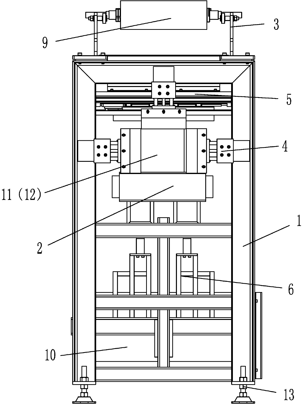
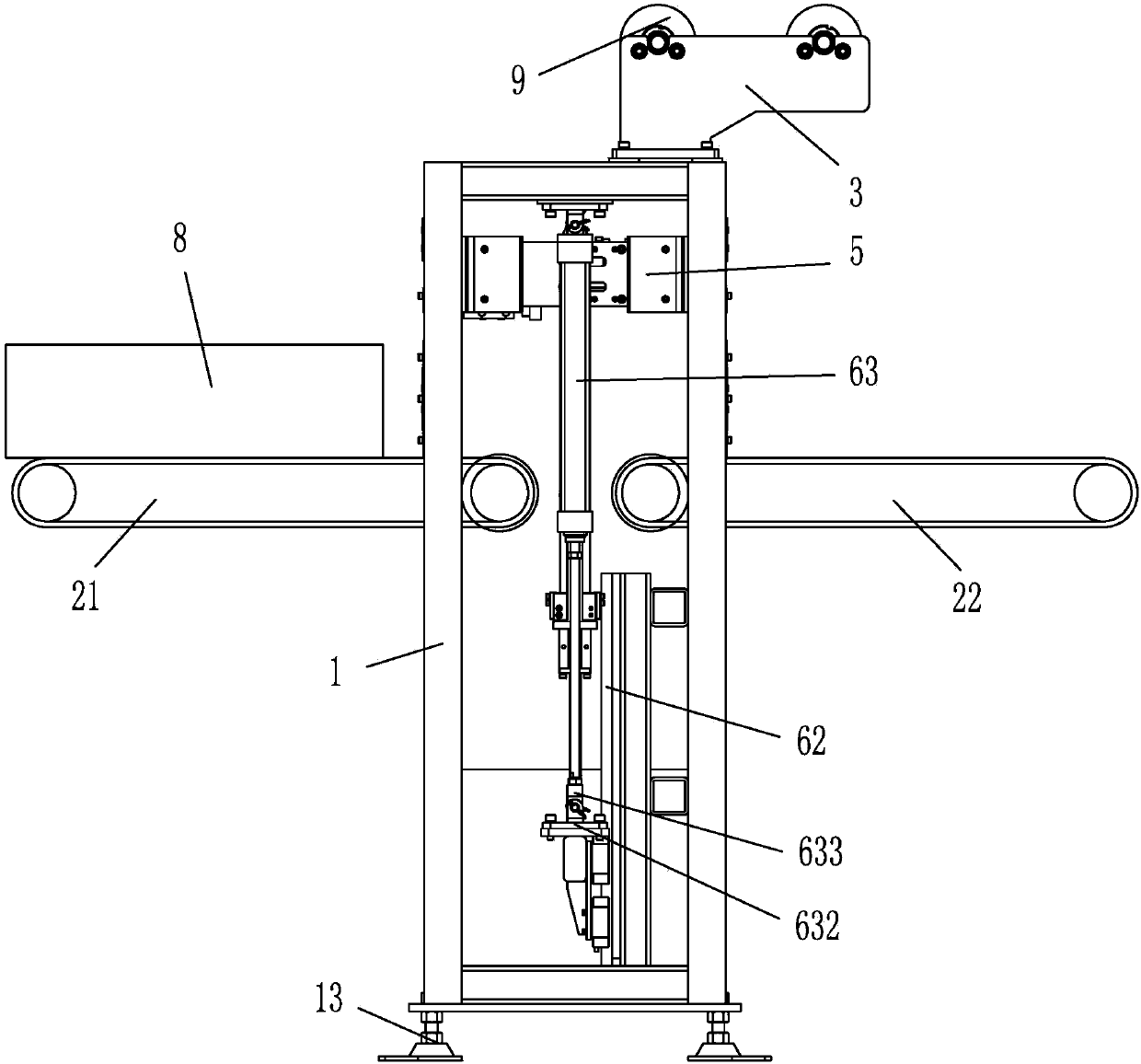
[0104] see Figure 1-Figure 3 , figure 1 It is a structural schematic diagram of a laminating machine according to an embodiment of the present invention, figure 2 It is a front view of a laminating machine according to an embodiment of the present invention, image 3 for figure 2 left view of . The present invention is used for the coating machine of catalyst end coating, comprises: Frame 1, as the basic structural part of whole equipment assembly, the parts and components of film coating machine are all assembled with this piece as a reference, and this frame 1 is for example It is a frame structure, preferably a welded structure, and its two sides are respectively provided with a workpiece inlet 11 and a workpiece outlet 12, and four adjustable feet 13 are installed at the bottom of the frame to adjust the height of t...


PUM


Abstract

The invention provides a film covering machine for film covering of the ends of catalysts and a film covering method of the film covering machine. The film covering machine comprises a machine frame, a conveying device, a film feeding device, a film drawing device, a film brushing device and a film cutting device, wherein the machine frame is provided with a workpiece inlet and a workpiece outlet; the conveying device is used for conveying a workpiece to be covered with a film and comprises a front conveying belt and a rear conveying belt, and the front conveying belt and the rear conveying belt are sequentially arranged corresponding to the workpiece inlet and the workpiece outlet and drive the workpiece to be covered with the film to pass through the machine frame; the film feeding device is installed on the machine frame, used for installing and supporting the film to be arranged, and located above the workpiece inlet and the workpiece outlet; the film drawing device is installed on the machine frame and arranged between the workpiece inlet and the workpiece outlet relative to the film feeding device, and can move vertically along the machine frame; the film brushing device is installed on the machine frame, used for brushing the film to be arranged on the surface of the workpiece to be covered with the film, and arranged at the workpiece inlet and the workpiece outlet relative to the film drawing device; the film cutting device is installed on the machine frame and arranged between the film feeding device and the film brushing device. The invention further discloses the film covering method of the film covering machine.

Description

technical field [0001] The invention relates to an automatic catalyst production equipment, in particular to a film coating machine and a film coating method applied to the catalyst end film coating in the automatic catalyst production. Background technique [0002] my country's coal-based energy structure is one of the main factors affecting the quality of my country's air environment. 90% of air pollution is sulfur dioxide and 67% of hydroxide comes from coal combustion. For the pollution control of hydroxide, people have done a lot of research work and formed many technologies, which are mainly divided into furnace control and furnace control. At present, the denitrification part of thermal power plants at home and abroad is controlled outside the furnace, and selective catalyst reduction (SCR) is mostly used to reduce the pollution of hydroxides. Among them, the catalyst is extruded from the extruder, cut into sections by a moving cutter, and needs to be dried in a calc...

Claims


Application Information

Patent Timeline
Patent Type & Authority Applications(China)
IPC IPC(8): B65B33/02B65B41/12B65B61/06
Inventor 刘尧生张金枝吴征南
Owner BEIJING RES INST OF AUTOMATION FOR MACHINERY IND
Why Eureka
Try Eureka