
Fireflooding moving type high-temperature electric ignition process pipe

A process string, mobile technology, applied in the fields of production fluids, wellbore/well components, earth-moving drilling, etc., can solve the problems of electric igniter and power cable burning, non-reusable, increased production cost, etc., to achieve rapid Ignition, prevent oxidation corrosion, reduce heat consumption

Inactive Publication Date: 2014-12-10
PETROCHINA CO LTD
View PDF9 Cites 12 Cited by
  • Summary
  • Abstract
  • Description
  • Claims
  • Application Information

AI Technical Summary

Problems solved by technology

[0004] The bundled igniter uses the oil pipe string to lower the igniter into the target layer, and its power cable is tied to the oil pipe to connect with the ground control cabinet. Since the gas injection pipe string cannot be released during the entire production cycle, after the end of the production cycle, the electric The igniter and power cable are burnt and cannot be reused, resulting in an increase in the production cost of a single well. There are many related patents and documents on the bundled electric igniter, so I won’t repeat them here
Chinese patent 201110326453.X introduces a removable electric igniter, which realizes the reuse of the igniter, but because the igniter and the power cable are not equal in diameter, during the production process of uninterrupted gas injection, when the wellhead is lifted and lowered Difficult and less secure
Chinese patent 201320112187.5 introduces a retractable electric ignition and monitoring system for fire-burning oil layer. The igniter has an equal-diameter structure and can be used repeatedly. However, the size of the mobile electric igniter limits its column structure to achieve high temperature There is still some difficulty in igniting the fire

Method used


Image

  • Fireflooding moving type high-temperature electric ignition process pipe

Examples


Embodiment Construction

[0022] In order to make the purpose, technical solutions and advantages of the embodiments of the present invention clearer, the technical solutions in the embodiments of the present invention will be clearly and completely described below in conjunction with the drawings in the embodiments of the present invention. Obviously, the described embodiments It is a part of embodiments of the present invention, but not all embodiments. Based on the embodiments of the present invention, all other embodiments obtained by persons of ordinary skill in the art without making creative efforts belong to the protection scope of the present invention.

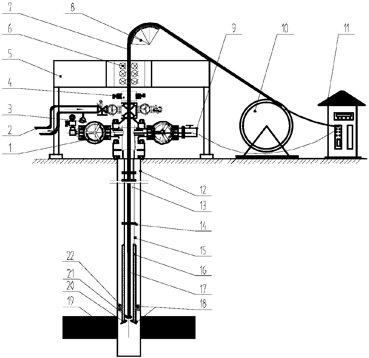
[0023] The invention specifically provides a fire-driven mobile high-temperature electric ignition process string, the process pipeline includes: casing, oil pipe, heat insulation pipe and packer; the hot end of the igniter of the fire-driven mobile high-temperature electric ignition set inside the heat-insulating pipe; the oil pipe is connec...


PUM


Abstract

The invention provides a fireflooding moving type high-temperature electric ignition process pipe. The pipe specifically comprises a casing pipe, an oil pipe, a heat insulation pipe and a packer, wherein the hot end of an igniter for fireflooding moving type high-temperature electric ignition is arranged in the heat insulation pipe, the oil pipe is connected with the top of the heat insulation pipe, a pipe body formed by the oil pipe and the heat insulation pipe in a combined mode is arranged in the casing pipe, and the packer is connected with the bottom of the heat insulation pipe and used for separating the pipe body formed by the oil pipe and the heat insulation pipe in the combined mode from the casing pipe. Due to the process pipe, the heat insulation effect can be effectively achieved, heat consumption is reduced and the casing pipe is protected; the process pipe plays a gas separation effect in a normal gas injection stage, and oxidation corrosion of oxygen to the pipe is also prevented; meanwhile, a channel is provided for a temperature measurement signal cable, an oil layer can be ignited at high temperature fast, the oil casing pipe is not damaged, and ignition operation can be safer, faster and more reliable.

Description

technical field [0001] The invention relates to the field of heavy oil development, in particular to a process string capable of realizing high-temperature ignition of a fire-driven mobile electric igniter. Background technique [0002] Liaohe Oilfield is the largest heavy oil production base in my country, and the heavy oil production accounts for about 60% of the total production. At present, most of the blocks are in the later stage of steam injection development, and the development difficulty is increasing. It is a practical way to use fire flooding as its replacement development method. The key to the successful development of fire flooding is the ignition of oil layers, and the high temperature ignition of oil layers and the high temperature oxidation of heavy oil layers are the guarantees for enhanced oil recovery. [0003] At present, the commonly used ignition methods at home and abroad are mainly divided into two categories: chemical injection ignition and electric...

Claims


Application Information

Patent Timeline
IPC IPC(8): E21B43/243
Inventor 张福兴杨显志刘利杨志祥程云龙赵树杰于晓聪王建骁许丹张成博王颖罗恩勇
Owner PETROCHINA CO LTD
Learn More