
Hydraulic pressure infinitely variable transmission for crawler

A continuously variable transmission and continuously variable speed technology, which is applied to vehicle gearboxes, vehicle parts, components with teeth, etc., can solve problems such as difficult control of clutch throttle and gear shifting, complicated shifting operations, and small changes in vehicle speed. To achieve the effect that is conducive to large load driving

Inactive Publication Date: 2014-12-10
吉首市宗南重工制造有限公司
View PDF6 Cites 15 Cited by
  • Summary
  • Abstract
  • Description
  • Claims
  • Application Information

AI Technical Summary

Problems solved by technology

Crawler tractors usually use a purely mechanical power transmission system to transmit power, which has the advantages of simple structure and high efficiency. However, the purely mechanical power transmission mechanism is complicated to shift gears during daily production and use. The skills of cars or tractors are difficult to control the coordination of clutch, accelerator and gear shifting, especially for beginner agricultural machinery operators, the steering control of crawler tractors is unstable, which may easily cause crawler tractors to overturn, thereby limiting the development of crawler tractors; and working in the field At this time, the engine of the crawler tractor is generally in a state of high throttle, which is close to the rated operating condition of the engine, the speed of the vehicle changes little, and the mechanical power and torque are relatively large, which easily leads to high energy consumption of the hydraulic system.

Method used


Image

  • Hydraulic pressure infinitely variable transmission for crawler
  • Hydraulic pressure infinitely variable transmission for crawler
  • Hydraulic pressure infinitely variable transmission for crawler

Examples


Embodiment Construction

[0033] In order to make the technical means, creative features, goals and effects achieved by the present invention easy to understand, the present invention will be further described below in conjunction with specific illustrations.

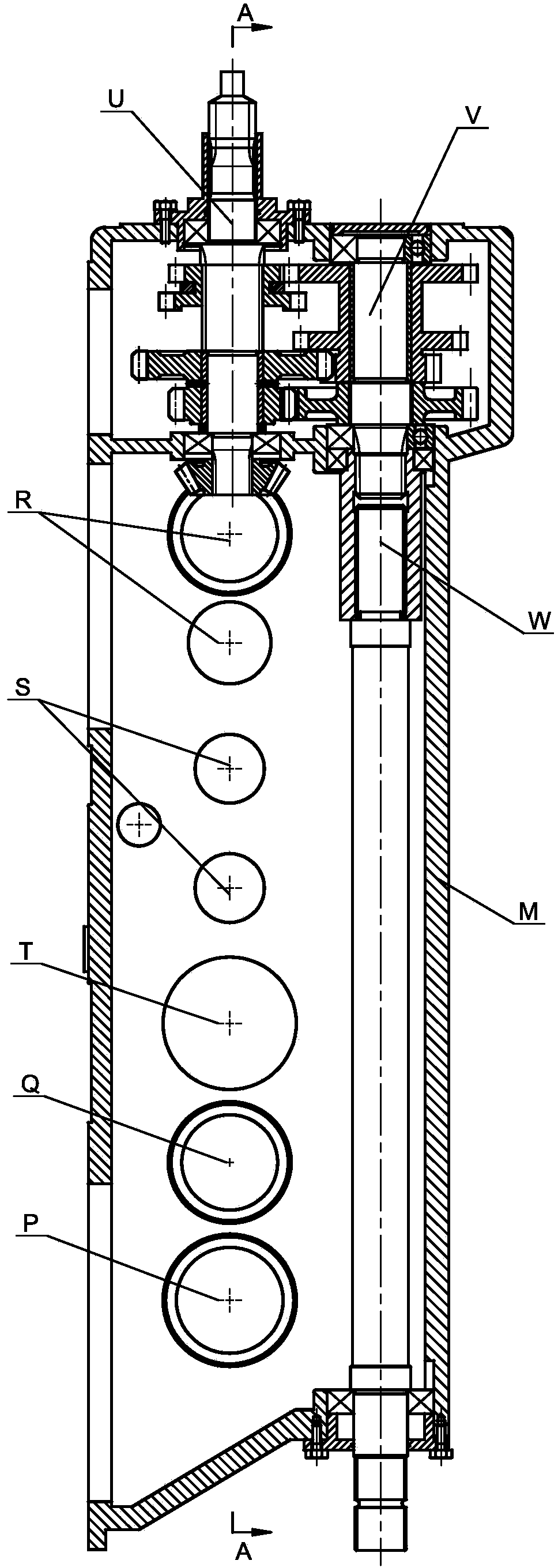
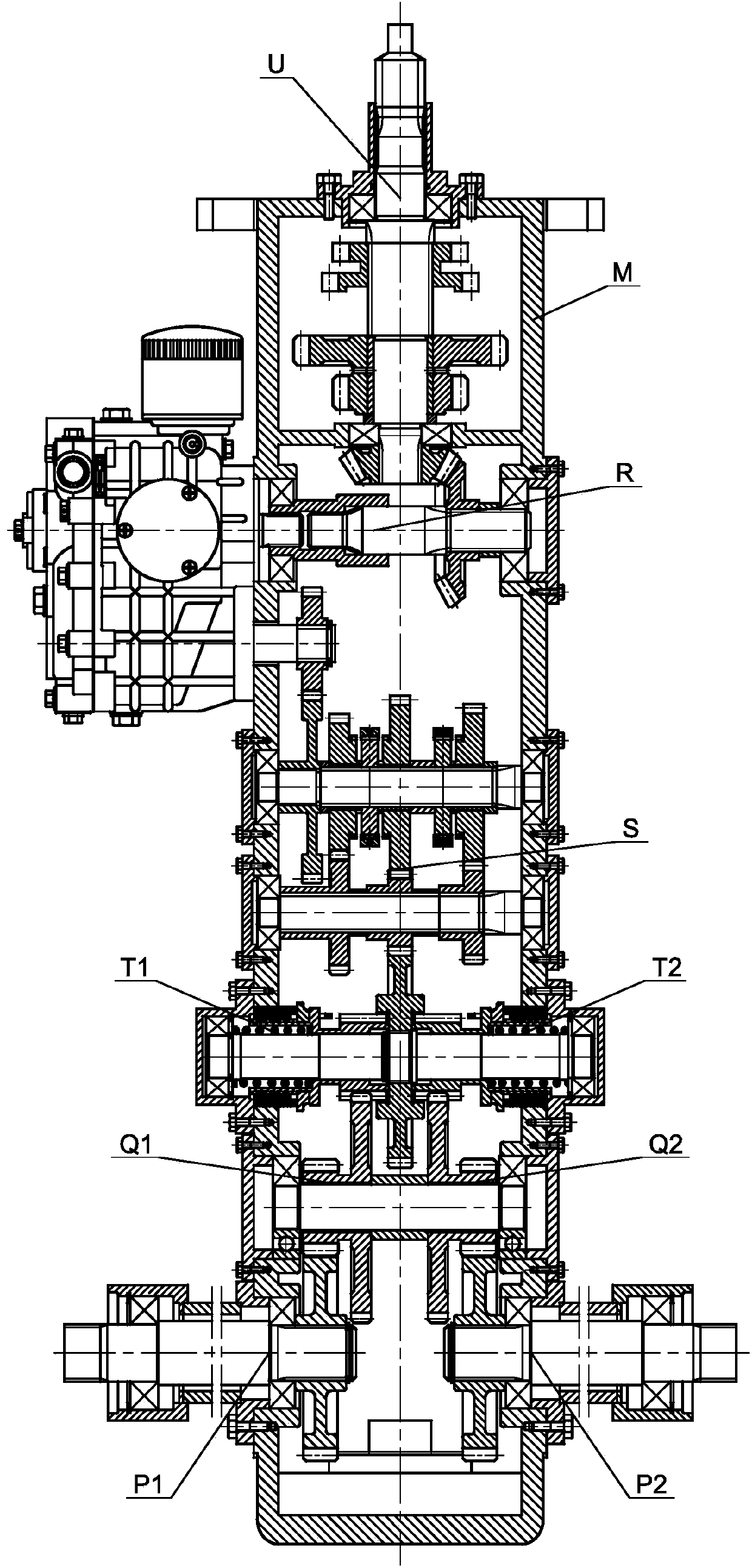
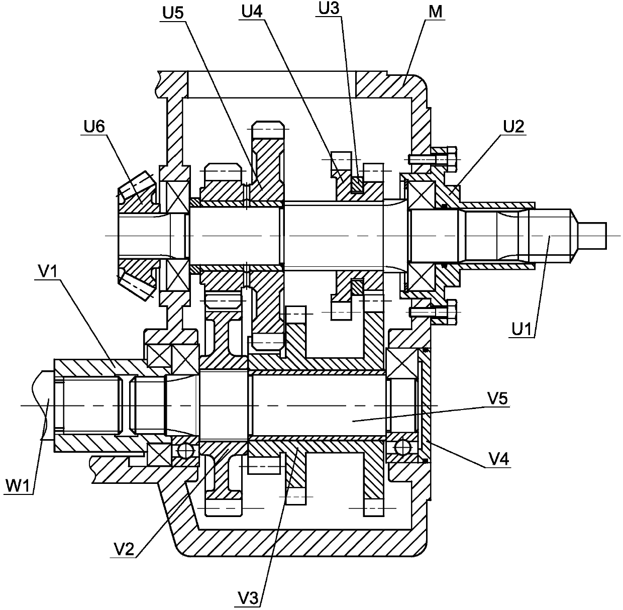
[0034] see Figure 1 ~ Figure 2 The tracked vehicle hydraulic continuously variable transmission includes the power input part U, the power output shaft deceleration part V, the power output shaft part W, the box M, the hydraulic continuously variable speed change part R, the mechanical shift part S, and the dog clutch steering control Part T, jaw clutch steering transmission part Q, left crawler drive part P1 and right crawler drive part P2; among them, power input part U, power output shaft deceleration part V, power output shaft part W, hydraulic stepless speed change The direction part R, the mechanical shift part S, the jaw clutch steering control part T, the jaw clutch steering transmission part Q, the left crawler drive part P1 and the ri...


PUM


Abstract

The invention discloses a hydraulic pressure infinitely variable transmission for a crawler. The hydraulic pressure infinitely variable transmission comprises a box body. The box body is provided with a power input part, a power output shaft deceleration part, a power output shaft part, a hydraulic pressure infinitely variable speed change reversing part, a mechanical gear shifting part, a jaw clutch steering control part, a jaw clutch steering drive part, a left caterpillar drive part and a right caterpillar drive part. One part of power of the power input part is output to the power output shaft part and used for external operation through the power output shaft deceleration part, and the other part of the power of the power input part is output to the mechanical gear shifting part through the hydraulic pressure infinitely variable speed change reversing part and output to drive the left caterpillar drive part and the right caterpillar drive part through the jaw clutch steering control part. According to the hydraulic pressure infinitely variable transmission, a hydraulic pump and a motor are integrally adopted for achieving infinitely variable drive speed change of a caterpillar tractor, infinitely variable speed changes when applied to operation, and operation is easy and convenient. The energy consumption is lowered, the operation convenience is improved, and left steering and right steering of a vehicle are achieved by controlling a left control rocker arm an a right control rocker arm respectively.

Description

technical field [0001] The invention relates to the technical field of agricultural machinery transmission, in particular to a hydraulic continuously variable transmission for crawler vehicles. Background technique [0002] Tracked vehicles mainly include tracked transport vehicles, tracked engineering vehicles and tracked tractors. In recent years, due to the wide ground area of ​​tracked tractors and the small compaction of the tracks on the soil, tracked tractors are used to attach implements to realize farming and harvesting. The mechanization of the rice field conforms to the requirements of the southern paddy field conservation tillage model, so it has developed rapidly. Crawler tractors usually use a purely mechanical power transmission system to transmit power, which has the advantages of simple structure and high efficiency. However, the purely mechanical power transmission mechanism is complicated to shift gears during daily production and use. The skills of cars ...

Claims


Application Information

Patent Timeline
Patent Type & Authority Applications(China)
IPC IPC(8): F16H47/06F16H57/023F16H63/30
CPCF16H47/06F16H57/023F16H63/30F16H2200/00
Inventor 李园平李学东赵文然龙爱海付乐陶肖慰
Owner 吉首市宗南重工制造有限公司
Learn More