
Multiple-factor accelerated aging test device for composite material electric pole

A composite material, accelerated aging technology, applied in measurement devices, analytical materials, instruments, etc., can solve problems such as wind deflection, galloping, aging, accelerated materials, etc., to achieve the effect of simplifying experimental operation, comprehensive testing, and convenient operation

Active Publication Date: 2014-12-10
WUHAN NARI LIABILITY OF STATE GRID ELECTRIC POWER RES INST +1
View PDF9 Cites 19 Cited by
  • Summary
  • Abstract
  • Description
  • Claims
  • Application Information

AI Technical Summary

Problems solved by technology

Specifically, in the natural environment, composite poles will face erosion from various external factors for a long time during operation. The more serious factors include high humidity in the atmosphere, alternating high and low temperatures, ultraviolet radiation, ozone and acid rain, etc. With the increase of time, the aging of the composite pole shaft will continue; at the same time, the wind deflection and galloping of the wire will also make the composite pole shaft in a swing state for a long time, which will cause the composite pole Stress relaxation fatigue aging; In addition, the strong electromagnetic field around the high-voltage wire will induce the polarization tendency of the polar groups in the material, which will affect the stability of the material and accelerate the aging of the material
[0004] Therefore, the existing aging experiments cannot comprehensively test the performance of composite poles, which brings safety hazards to the subsequent use of composite poles

Method used


Image

  • Multiple-factor accelerated aging test device for composite material electric pole
  • Multiple-factor accelerated aging test device for composite material electric pole

Examples


Embodiment Construction

[0020] The present invention will be described in further detail below in conjunction with the accompanying drawings and embodiments, but these embodiments should not be construed as limiting the present invention.

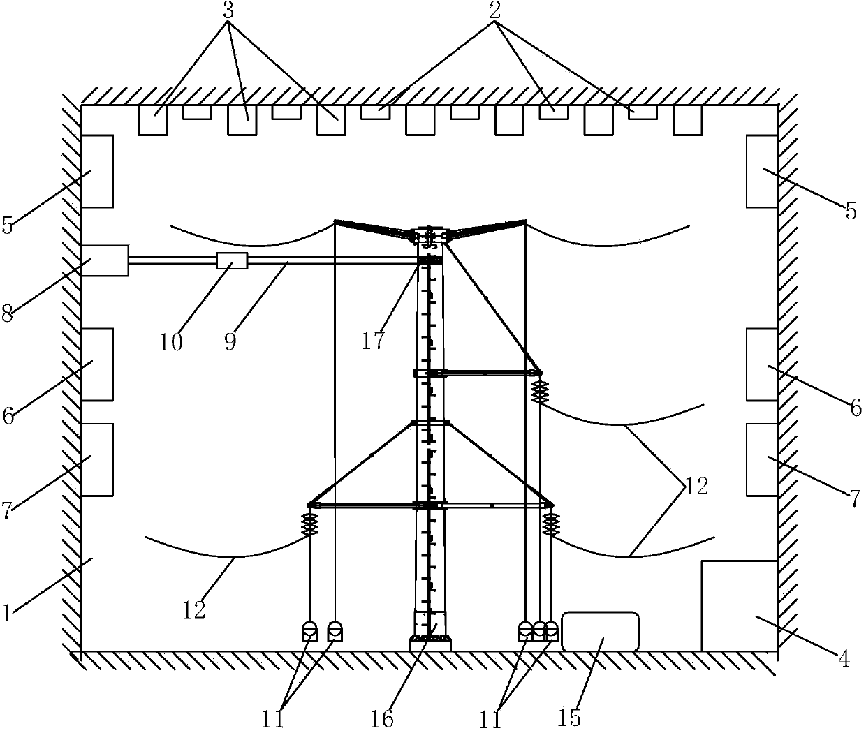
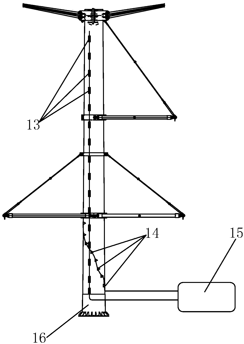
[0021] Such as figure 1 As shown, this embodiment discloses a multi-factor accelerated aging experiment device for composite poles, including an aging laboratory 1, and the top surface of the aging laboratory 1 is respectively provided with a water nozzle 2 for simulating a rainwater environment and a water nozzle for simulating a rainwater environment. Cooperate with the acid-base salt sprayer 3 of the water nozzle 2 to simulate the acid rain environment, the side wall of the aging laboratory 1 is respectively provided with an ozone generator 5 for simulating the ozone environment, an ultraviolet lamp 6 for simulating the ultraviolet radiation environment and a A high and low temperature humid heater 7 simulating an alternating high and low temperature environmen...


PUM


Abstract

The invention discloses a multiple-factor accelerated aging test device for a composite material electric pole. The multiple-factor accelerated aging test device comprises an aging test room, wherein water nozzles and acid, alkali and salt atomizers are arranged on the roof surface of the aging test room; ozone generators, ultraviolet lamps, high-temperature and low-temperature humidity-heat devices, and a tensile machine are arranged on the side walls of the aging test room respectively; the action end of the tensile machine is connected with a traction rod which is provided with a force meter; corresponding to the composite material electric pole to be tested, weights, leads, longitudinal strain gratings, circumferential strain gratings, and a signal detection processor which is electrically connected with the force meter, the longitudinal strain gratings and the circumferential strain gratings respectively, are arranged inside the aging test room. By the cooperation of the water nozzles, the acid, alkali and salt atomizers, the ozone generators, the ultraviolet lamps, the high-temperature and low-temperature humidity-heat devices, the tensile machine, the weights and the leads, various natural environments can be simulated comprehensively, so that the performance of the composite material electric pole can be thoughtfully and correctly tested. The accelerated aging test device is applicable to testing of pole towers.

Description

technical field [0001] The invention relates to a pole aging experiment device, in particular to a composite material pole multi-factor accelerated aging experiment device. Background technique [0002] With the rapid development of new materials, composite poles have emerged as the times require, which can solve the problems of traditional poles such as high mass, difficulties in transportation, installation and maintenance, and high flashover accident rate, and have attracted wide attention. In order to ensure the safe and long-term operation of composite poles, the weather aging performance test of composite poles used outdoors must be carried out. [0003] At present, for the aging experiment of composite poles, generally only one or two external conditions are simulated for aging behavior experiments. Although this kind of aging experiment can test the performance of composite poles to a certain extent, composite materials used outdoors When the pole is in actual opera...

Claims


Application Information

Patent Timeline
IPC IPC(8): G01N17/00
Inventor 吴雄胡虔潘吉林梅端彭家顺朱晓东何昌林
Owner WUHAN NARI LIABILITY OF STATE GRID ELECTRIC POWER RES INST
Learn More