Visibility calibration instrument, calibration system and product machine calibration method based on calibration system

A visibility and calibration technology, applied in the direction of instrumentation, transmittance measurement, etc., can solve the problems of inaccurate calibration, inconsistent scattering, low precision, etc., and achieve the effect of accurate data calibration, good performance consistency and high measurement accuracy

Active Publication Date: 2014-12-10
SICHUAN DINGLIN INFORMATION TECH
View PDF6 Cites 11 Cited by
  • Summary
  • Abstract
  • Description
  • Claims
  • Application Information

AI Technical Summary

Problems solved by technology

However, the disadvantages of this method are: 1) The accuracy of the working machine itself is difficult to guarantee, and the accuracy of the working machine depends on the data obtained by the observer to calibrate the working machine, and the boundary between "visible" and "invisible" of the target is not clear. Clarity, coupled with visual contrast, the threshold of visual perception and illuminance vary greatly with lighting conditions and psychological influences, so there must be a large error in the manual visual inspection of visibility to calibrate the working machine; 2) Due to the large human factors in the calibration process , so the accuracy of the main machine is difficult to be confirmed by a third party, and it is difficult to form a standard; 3) The long-term performance of the main machine and whether there will be data drift in various climatic environments cannot be effectively guaranteed, and the calibration process is affected by weather, climate and site environment 4) It is difficult for the bulky working machine to complete the on-site calibration of the product machine of the visibility meter
[0011] The disadvantages of this method are: 1) The scattering standard device based on the scatterometer is the same as the scatterometer to obtain the visibility data indirectly, there is a conversion error, and it is inconsistent with the scattering of the air, and some aerosol particles in the air are absorbed by the measuring beam instead Can not scatter
2) Standard reflectors with different reflective rates are equivalent to scattering rate and visibility data are also not convincing, and it is difficult to obtain third-party approval and monitoring
[0013] The disadvantage of this method is that although the low-visibility measurement accuracy of the transmissometer is very strong, and the high-visibility measurement accuracy of the scatterometer is strong, but in the state where the reference does not exist, there must be problems in the mutual guarantee calibration
2) The scattering meter is a low-end visibility meter, which has the disadvantage of inconsistent scattering with the air, and some aerosol particles in the air absorb the measuring beam but cannot scatter, so it cannot be accurately calibrated for high-end transmissometers
[0014] To sum up, the traditional calibration method of the visibility meter has low precision, cannot directly reflect and meet the definition of visibility, and cannot provide the visibility benchmark and data tested or recognized by a third party for the calibration of the visibility meter

Method used


Image

  • Visibility calibration instrument, calibration system and product machine calibration method based on calibration system
  • Visibility calibration instrument, calibration system and product machine calibration method based on calibration system
  • Visibility calibration instrument, calibration system and product machine calibration method based on calibration system

Examples


Embodiment

[0067] In this example, the operation steps of the calibration method of the product machine based on the visibility calibration system are as follows:

[0068] 1) Calibrate the calibration instrument, that is, transfer the original reference to the first-level reference:

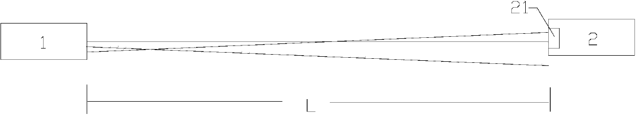
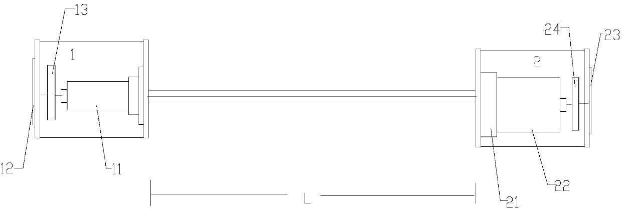
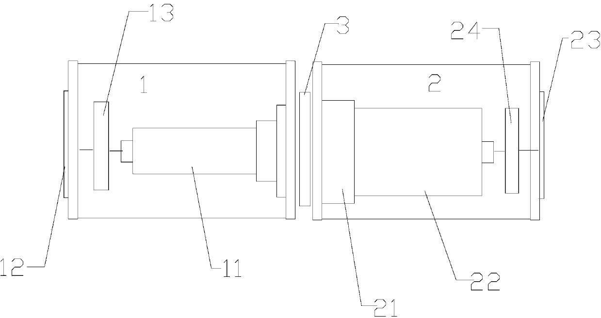
[0069] In a clean room, the specific indicators of each instrument are: the collimated beam of the transmitter of the calibrator is 30 mm in diameter, the luminous flux is B1 = 12 lumens, and the diameter of the receiving lens is 80 mm to ensure that all collimated light can be received. There are 3 optical attenuation sheets, corresponding to the three types of visibility, high, medium and low. As the original benchmark, it is a measurement benchmark, and its performance is recognized by the authority. The original benchmark equivalent extinction coefficient or visibility data. According to the visibility calculation formula MOR=ln0.05 / σ=L*ln0.05 / lnT, the data in Table 1 can be obtained.

[0070] Table 1 Compari...


PUM


Abstract

The invention relates to the field of visibility measurement and provides a visibility calibration instrument and a calibration system which can be detected and accepted by a third party, and a product machine calibration method based on the calibration system. With the adoption of the technical scheme, the visibility calibration instrument comprises a transmitter and a receiver, wherein the transmitter comprises a light source module, a first data display operation screen and a first signal processing module; the light source module is connected with the first signal processing module; the first signal processing module is connected with the first data display operation screen; light beams emitted by the light source module are collimating beams; the receiver comprises a receiving lens, a photoelectric detector, a second data display operation screen and a second signal processing module; the receiving lens and the photoelectric detector are sequentially arranged along a light path; total light beams emitted by the transmitter drop into the receiving lens; the photoelectric detector is connected with the second signal processing module; the second signal processing module is connected with the second signal data display operation screen. The visibility calibration instrument is applicable to calibration of a visibility meter.

Description

Technical field [0001] The invention relates to the field of visibility measurement, in particular to a visibility calibration instrument, a calibration system and a calibration method for a product machine based on it. Background technique [0002] A visibility meter is an instrument that obtains atmospheric visibility values ​​by measuring the extinction coefficient of a horizontal air column at a limited distance. The transmissive visibility meter is a kind of instrumental visibility meter that best meets the definition of visibility by the International Meteorological Organization. Its principle is to obtain the atmospheric meteorological optical distance MOR by sampling a horizontal air column of a certain length L and measuring its extinction coefficient σ. Meteorological optical distance, namely visibility MOR, is defined as the length of the path through which the luminous flux of a parallel beam with a color temperature of 2700K emitted by an incandescent lamp is weakene...

Claims


Application Information

Patent Timeline
Patent Type & Authority Applications(China)
IPC IPC(8): G01N21/59G01W1/18
Inventor 甘志刘庆蔡琴
Owner SICHUAN DINGLIN INFORMATION TECH
Why Eureka
Try Eureka