Microstrip line phase shifter based on LTCC technology

A technology of microstrip line and phase shifter, which is applied to waveguide-type devices, electrical components, circuits, etc., can solve the problems of large size, inability to miniaturize, and difficult to miniaturize the magnetizing circuit, and achieves overcoming process sensitivity and realizing miniaturization. effect of reduction, volume and mass reduction

Inactive Publication Date: 2014-12-10
UNIV OF ELECTRONICS SCI & TECH OF CHINA
View PDF2 Cites 6 Cited by
  • Summary
  • Abstract
  • Description
  • Claims
  • Application Information

AI Technical Summary

Problems solved by technology

The waveguide transmission type ferrite phase shifter, the size of the waveguide is determined by the wavelength of the propagated electromagnetic wave, so it is difficult to miniaturize; the stripline and microstrip line type phase shifters can reduce the size, but the stripline phase shifter requires iron Oxygen and dielectric ceramics are co-fired, and the shrinkage rate of ferrite materials in different systems is different, so the yield is strictly controlled by the process; although the microstrip line phase shifter is not limited by the above process, the volume of the magnetization circuit of its current structure huge
As reported in the literature [Xi Yang, Jing Wu, etc.Compact and Low Loss Phase Shifter With Low Bias Field Using Partially Magnetized Ferrite.IEEE Tran.on magn.49(7):3882-3885] based on YIG substrate microstrip Line phase shifter, the structure of the phase shifter is designed with 9 sections of meandering coupled microstrip metal lines on the YIG rectangular substrate, but the phase shifter needs to magnetize the YIG substrate in an external electromagnet, so it still cannot miniaturization

Method used


Image

  • Microstrip line phase shifter based on LTCC technology
  • Microstrip line phase shifter based on LTCC technology
  • Microstrip line phase shifter based on LTCC technology

Examples


Embodiment Construction

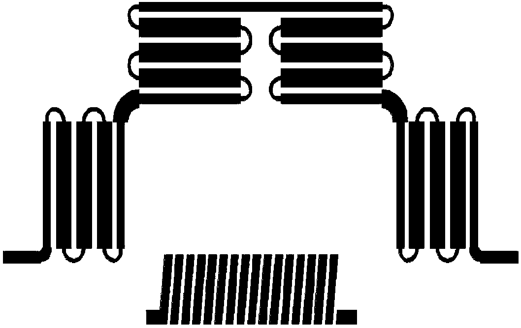
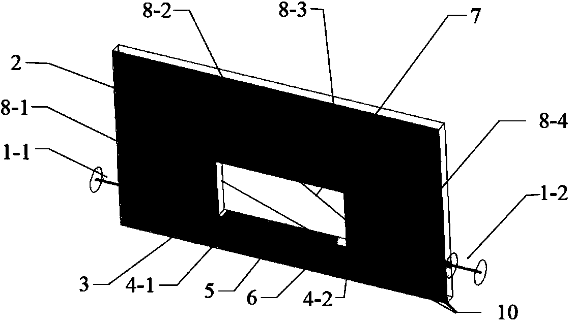
[0029] The phase shift excellent value parameter and reflection parameter of the present invention are mainly determined by the intrinsic parameters of the ferrite substrate material, the thickness of the ferrite substrate, and the length of the curved coupling microstrip line. The present invention will be further described in detail below in conjunction with specific embodiments and accompanying drawings, but the present invention is not limited thereto.

[0030] The simulation results of the microstrip line phase shifter based on LTCC technology are as follows: Figure 6 to Figure 8 As shown, the center frequency is 11.5GHz, the bandwidth is 3.5GHz, the insertion loss within the bandwidth is <1.1dB, and the phase shift figure of merit is 290° / dB. The physical size of the phase shifter is: length*width*height=28mm*16mm*1.01mm, which is smaller than the conventional waveguide type phase shifter and close to the physical size of the microstrip ferrite phase shifter.

[0031] ...


PUM


Abstract

The invention provides a microstrip line phase shifter based on LTCC technology. The microstrip line phase shifter comprises a rectangular ferrite substrate, a first coupling curved segment, a second coupling curved segment, a third coupling curved segment, a fourth coupling curved segment, a solenoid and a bonding pad, and is characterized in that, the center of the rectangular ferrite substrate is provided with a rectangular substrate window; the fourth coupling curved segments are distributed on the upper surface of the substrate, wherein the first and fourth coupling curved segments are respectively positioned on the ferrite substrate on two sides of the wide side of the substrate window, and the second and third coupling curved segments are arranged on the ferrite substrate on one side of the long side of the substrate window in parallel, the solenoid is arranged on the ferrite substrate on the other side of the long side of the substrate window and forms a winding structure with the ferrite substrate, and the head end and tail end of the winding structure are connected to the bonding pad through wires. The microstrip line phase shifter has the advantages of low insertion loss and large average power capacity, a magnetization cycle is integrated into the ferrite substrate, so that the volume of the common ferrite phase shifter is significantly reduced, and miniaturization of the phase shifter is facilitated.

Description

technical field [0001] The invention belongs to the field of microwave communication devices, in particular to a miniaturized microstrip ferrite phase shifter based on LTCC technology. Background technique [0002] The phase shifter used in the microwave communication field is mainly used to change the phase of the microwave signal. The phase shifter is required to have the characteristics of small insertion loss, small reflection, large phase shift, and small volume. There are three main types of common phase shifters. The first type is based on semiconductor devices (such as PIN diodes, MMICs, etc.) to design switch array phase shifters; the second type is MEMS phase shifters based on MEMS technology; the third type is based on microwave Ceramic material phase shifters, microwave ceramic materials used in phase shifters mainly include microwave dielectric materials (such as: BST, etc.) and magnetic ferrite materials (such as: YIG, LiZn, etc.), ferrite phase shifters are i...

Claims


Application Information

Patent Timeline
Patent Type & Authority Applications(China)
IPC IPC(8): H01P1/195
Inventor 杨青慧王明郝欣欣张怀武贾利军廖宇龙文岐业
Owner UNIV OF ELECTRONICS SCI & TECH OF CHINA
Why Eureka
Try Eureka