Frequency-reconfigurable triple-band antenna and method

An antenna and frequency technology, which is applied in the field of frequency reconfigurable tri-band antenna and wireless communication system, can solve the problems of increasing the difficulty of antenna design and manufacturing cost, complex structure, and the inability to realize independent adjustment of working frequency bands, etc., and achieve low price , wide application space, simple structure effect

Active Publication Date: 2014-12-10
XIDIAN UNIV
View PDF18 Cites 6 Cited by
  • Summary
  • Abstract
  • Description
  • Claims
  • Application Information

AI Technical Summary

Problems solved by technology

However, this invention requires a feed circuit and has a relatively complicated structure, which undoubtedly increases the design difficulty and manufacturing cost of the antenna. In addition, the antenna cannot realize the independent adjustment of each working frequency band.
Another example is the document "Frequency-reconfigurable Dual-band Monopole Antenna for WiMAX Wireless Devices, X. L. Sun, S. W. Cheung, and T. I. Yuk, MICROWAVE AND OPTICAL TECHNOLOGY LETTERS, VOL. 56, NO. 1, PP. 49-55, January 2014" A dual-frequency antenna designed to adjust the capacitance loaded on the radiation patch to achieve frequency reconfigurability, but this antenna only covers the WiMAX frequency band, and can only achieve adjustable frequency points for the two frequency bands, and cannot pass Adjust the loading capacitor to complete the switching between single-frequency / dual-frequency working states

Method used


Image

  • Frequency-reconfigurable triple-band antenna and method
  • Frequency-reconfigurable triple-band antenna and method
  • Frequency-reconfigurable triple-band antenna and method

Examples


Embodiment Construction

[0035] The present invention will be further described below in conjunction with embodiment accompanying drawing:

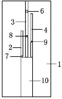
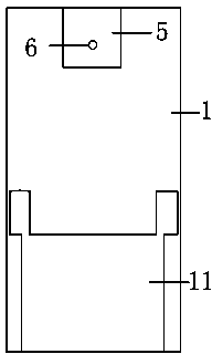
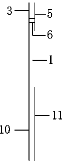
[0036] see figure 1 , figure 2 with image 3, a frequency reconfigurable tri-band antenna, comprising: a dielectric substrate 1, an upper radiation patch, and a lower radiation patch 5, wherein the upper radiation patch consists of the first part 2 of the upper radiation patch, the second part of the upper radiation patch Two parts 3, the third part 4 of the upper radiation patch; the first part 2 of the upper radiation patch, the second part 3 of the upper radiation patch, and the third part 4 of the upper radiation patch are located on the upper layer of the dielectric substrate 1, The second part 3 of the upper radiating patch is connected to the lower radiating patch 5 through a metallized via 6 to form a radiating unit, and the first inductance 7, the second inductance 8, and the third inductance 9 are respectively located in the first part of the upper r...


PUM


Abstract

The invention relates to a frequency-reconfigurable triple-band antenna and a method. The antenna comprises a medium substrate, an upper layer radiation sticker and a lower layer radiation sticker, wherein the upper layer radiation sticker consists of a first portion of the upper layer radiation sticker, a second portion of the upper layer radiation sticker and a third portion of the upper layer radiation sticker; the first portion of the upper layer radiation sticker, the second portion of the upper layer radiation sticker and the third portion of the upper layer radiation sticker are positioned on the upper layer of the medium substrate; the second portion of the upper layer radiation sticker and the lower layer radiation sticker are connected through a metallization through hole, thereby constructing a radiation unit; a first inductor, a second inductor and a third inductor are positioned on the first portion of the upper layer radiation sticker, the second portion of the upper layer radiation sticker and the third portion of the upper layer radiation sticker respectively to realize independent control of three frequency bands. The frequency-reconfigurable triple-band antenna and the method can be applied to a 2.4/5.2/5.8GHz WLAN (Wireless Local Area Network) and 3.5/5.5GHz WiMAX (Worldwide Interoperability for Microwave Access), and the radiation direction of the antenna is kept basically invariable.

Description

technical field [0001] The invention belongs to the field of antennas, in particular to a frequency reconfigurable tri-band antenna and method, which are applied to wireless communication systems. Background technique [0002] In recent years, with the rapid development of wireless communications, especially Wireless Local Area Network (WLAN) and Worldwide Interconnection for Microwave Access (WiMAX), tri-band antennas applied to WLAN and WiMAX frequency bands have become a research hotspot for many experts and scholars. With the proposal of many tri-band antennas, the performance requirements of the antenna itself are getting higher and higher, and the frequency reconfigurability of the antenna has become a very important indicator because of its frequency band flexibility in practical engineering applications. Therefore, it is very meaningful to design and implement a reconfigurable antenna that realizes frequency by loading tunable components. At present, some methods to...

Claims


Application Information

Patent Timeline
Patent Type & Authority Applications(China)
IPC IPC(8): H01Q1/38H01Q5/00H01Q9/04H01Q23/00
Inventor 翟会清詹传汉刘露梁昌洪
Owner XIDIAN UNIV
Why Eureka
Try Eureka