
Lossless thyristor driving circuit

A thyristor drive, thyristor technology, applied in logic circuits, electrical components, pulse technology, etc., can solve problems such as power consumption and loss, and achieve the effects of reducing drive circuit loss, improving reliability, and reducing area

Active Publication Date: 2014-12-10
EAST GRP CO LTD
View PDF4 Cites 3 Cited by
  • Summary
  • Abstract
  • Description
  • Claims
  • Application Information

AI Technical Summary

Problems solved by technology

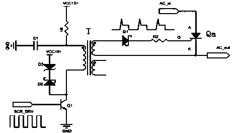
[0009] From the above analysis, it can be seen that there is current flowing through R1 in stages 1, 2, 3, and 4, and serious power consumption is generated in R1, and in stage 4 The remagnetization of the transformer is carried out by absorbing energy through the voltage regulator tube D3, so this separate drive circuit is a lossy drive

Method used


Image

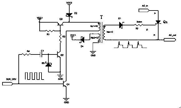
  • Lossless thyristor driving circuit
  • Lossless thyristor driving circuit
  • Lossless thyristor driving circuit

Examples


Embodiment Construction

[0018] The technical solutions in the embodiments of the present invention are clearly and completely described below in conjunction with the accompanying drawings in the embodiments of the present invention. Obviously, the described embodiments are only part of the embodiments of the present invention, not all of them. Based on the embodiments of the present invention, all other embodiments obtained by persons of ordinary skill in the art without making creative efforts belong to the protection scope of the present invention.

[0019] In the following description, a lot of specific details are set forth in order to fully understand the present invention, but the present invention can also be implemented in other ways different from those described here, and those skilled in the art can do it without departing from the meaning of the present invention. By analogy, the present invention is therefore not limited to the specific examples disclosed below.

[0020] Such as figure...


PUM


Abstract

The invention discloses a lossless thyristor driving circuit, and relates to the technical field of thyristor driving circuits. The lossless thyristor driving circuit comprises a thyristor Qa, a resistor R2, a rectifying diode D1, triodes Q1-Q3, diodes D2-D4, a resistor R1, resistors R3-R4, a capacitor C1 and a transformer T, wherein lossless driving is completely realized on the primary side of the transformer in the driving circuit. Compared with a lossy driving circuit (Fig. 2), the driving circuit is additionally provided with a VCC2 power supply of which the value is lower than that of VCC1. The VCC1 is used for providing peak driving current for the thyristor, and the VCC2 is used for providing platform driving current for the thyristor. The VCC2 can be obtained by using the VCC1 and a simple switch step-down chip. Through the driving circuit, the driving circuit loss, the demand of power supply power, the driving cost and the temperature of the driving circuit are lowered effectively, the area of a thyristor driving plate is reduced, and the reliability of the driving circuit is improved.

Description

technical field [0001] The invention relates to the technical field of thyristor drive circuits, in particular to a lossless thyristor drive circuit. Background technique [0002] At present, thyristor driving methods are roughly divided into the following two types, one is external drive and the other is self-drive. Lossy high-frequency isolated pulse drive (hereinafter referred to as lossy drive) is widely used in the external drive mode. The principle block diagram is as follows: figure 2 shown. Qa is the driven thyristor, T is the high-frequency isolation transformer, D1 is the rectifier diode, D2, D3 are the diodes and voltage regulator tubes for transformer remagnetization, R1 and R2 are the current limiting resistors, C1 is the pulse driving support capacitor, Q1 is Drive the triode, SCR_DRV is the driving signal of the thyristor. [0003] Its circuit operation is divided into four stages: [0004] Phase 1: When SCR_DRV is low, Q1 is turned off, driving the curren...

Claims


Application Information

Patent Timeline
Patent Type & Authority Applications(China)
IPC IPC(8): H03K19/082
Inventor 崔彬余仕君谢文贵
Owner EAST GRP CO LTD
Learn More