Pipeline multipoint synchronous automatic welding process

A welding process, synchronous and automatic technology, applied in welding equipment, manufacturing tools, metal processing, etc., can solve the problems of weld stress concentration, limited space for improving welding efficiency, and incomplete penetration, so as to eliminate stress concentration and improve welding quality. Efficiency, small volume effect

Active Publication Date: 2014-12-17
BC P INC CHINA NAT PETROLEUM CORP +2
View PDF7 Cites 7 Cited by
  • Summary
  • Abstract
  • Description
  • Claims
  • Application Information

AI Technical Summary

Problems solved by technology

However, most of the all-position automatic welding technologies currently in use are single-torch automatic welding or double-torch automatic welding, and the welding method is mostly downward welding. The single-torch welding gun or double-torch welding gun is driven by its moving carrier Next, weld from the 12 o'clock position to the 6 o'clock position of the pipeline. After the single-layer welding is completed, the moving carrier needs to return to the 12 o'clock position to prepare fo

Method used


Image

  • Pipeline multipoint synchronous automatic welding process
  • Pipeline multipoint synchronous automatic welding process
  • Pipeline multipoint synchronous automatic welding process

Examples


Embodiment

[0024] refer to Figures 1 to 8 Embodiments of the present invention are further described:

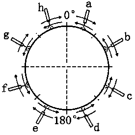
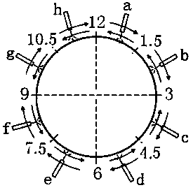
[0025] This welding process adopts eight welding torch pipeline synchronous automatic welding internal welding machine, which has eight welding torches, namely the first welding torch a, the second welding torch b, the third welding torch c, the fourth welding torch d, the fifth welding torch e, and the sixth welding torch f The seventh welding gun g and the eighth welding gun h, the welding length of each welding gun is 1 / 8 of the outer circumference of the pipeline. The 1.5 o'clock, 3 o'clock, 4.5 o'clock, 6 o'clock, 7.5 o'clock, 9 o'clock, 10.5 o'clock and 12 o'clock positions of the pipeline are the overlapping areas of the weld joints, and the sensing range of the angle sensor is the outer arc of the pipeline corresponding to the central angle of 0.5° Long (0.5 / 360×π×D). The first torch a to the fourth torch d are used for segmental independent welding on the 0°-180° side of th...


PUM

PropertyMeasurementUnit
Arc radiusaaaaaaaaaa

Abstract

The invention discloses a pipeline multipoint synchronous automatic welding process used for root welding conducted through an inner welding machine. The process is designed for increasing the welding speed. According to the welding process, the eight-welding-torch pipeline synchronous automatic welding inner welding machine is adopted, a first welding gun, a second welding gun, a third welding gun and a fourth welding gun are used for segmented independent welding on the side ranging from 0 degree to 80 degrees of a pipeline, the fifth welding gun, the sixth welding gun, the seventh welding gun and the eighth welding gun are used for segmented independent welding on the side ranging from 180 degrees to 0 degree of the pipeline, and the welding directions, on the two sides of the pipeline, of the welding machine are opposite. The process includes the steps that a specially-designed U-shaped groove is formed in the end of the large-caliber oil and gas pipeline; the inner welding machine is aligned with the pipeline; welding parameters of the inner welding machine are adjusted; root welding of the groove is conducted through the inner welding machine; thermal welding, filling welding and cosmetic welding of a weld joint are conducted; after the whole annular joint is welded completely, an arc is quenched. In the welding process, the U-shaped groove of the weld joint is small, the volume needing to be filled is small, the welding speed can be increased three to four times, and construction efficiency is improved to a great extent. Welding stress can be evenly distributed through segmented multipoint synchronous welding, potential safety hazards caused by stress concentration are eliminated, and the welding pass percent is kept over 97%.

Description

technical field [0001] The invention relates to a pipeline multi-point synchronous automatic welding process, which belongs to the technical field of petroleum and natural gas pipeline welding. Background technique [0002] With the rapid growth of oil and gas energy consumption demand and the increasing progress of science and technology, the construction of oil and gas pipelines has entered a peak period and is developing towards high-efficiency construction. The speed and quality of pipeline construction have gradually become the focus of attention of construction parties, especially Especially welding efficiency, which is a key link in pipeline construction, has attracted much attention. At present, pipeline construction has transitioned from manual welding to semi-automatic welding and automatic welding. Automatic welding equipment has fast welding speed, high efficiency and simple operation, which greatly reduces the labor intensity of welders. With the popularization...

Claims


Application Information

Patent Timeline
IPC IPC(8): B23K9/16B23K9/235B23K33/00
CPCB23K9/007B23K9/0282B23K9/164B23K9/235B23K33/006B23K2101/06
Inventor 张锋王长江王鲁君胡立新闫臣张毅马志锋吴江桥刘然杜长春单慕晓
Owner BC P INC CHINA NAT PETROLEUM CORP
Why Eureka
Try Eureka