Co-extrusion molding device for wood plastic-solid wood composite material

A composite material and forming device technology, applied in the direction of coating, etc., can solve problems such as extrusion of solid wood materials that are not suitable for rigidity, and achieve the effects of improving material processing performance and interface performance, improving interface bonding strength, and improving comprehensive mechanical properties

Active Publication Date: 2014-12-17
王清文
View PDF5 Cites 15 Cited by
  • Summary
  • Abstract
  • Description
  • Claims
  • Application Information

AI Technical Summary

Problems solved by technology

[0004] The purpose of the present invention is to solve the problem that the existing wood-plastic co-extrusion unit is not suitable for extruding rigid solid wood materials

Method used


Image

  • Co-extrusion molding device for wood plastic-solid wood composite material
  • Co-extrusion molding device for wood plastic-solid wood composite material
  • Co-extrusion molding device for wood plastic-solid wood composite material

Examples


specific Embodiment approach 1

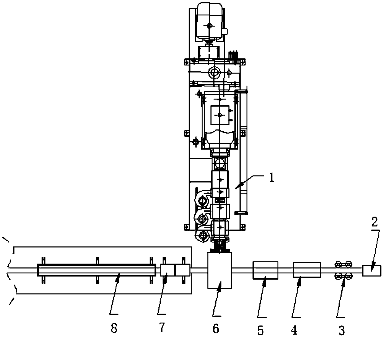
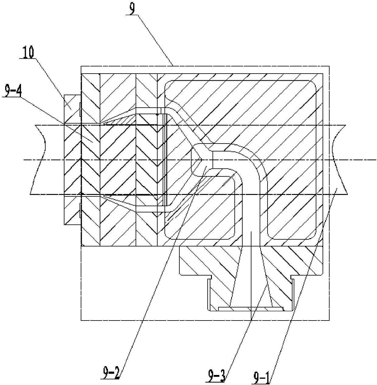
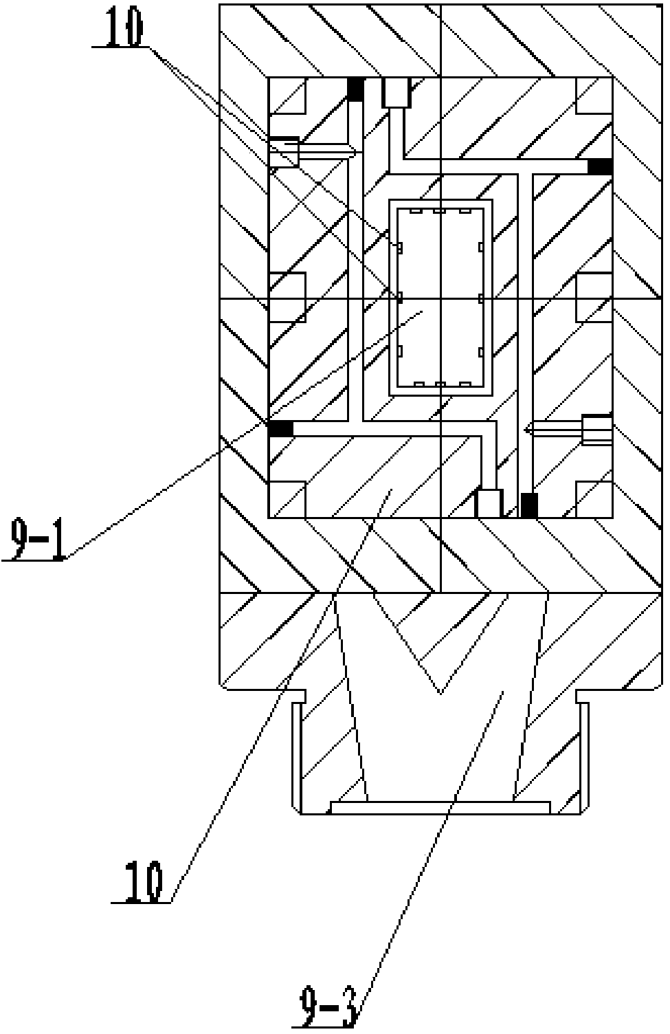
[0013] Specific implementation mode one: combine figure 1 , figure 2 and image 3 Describe this embodiment, a kind of wood-plastic solid wood composite material co-extrusion molding device of this embodiment comprises wood-plastic extruder 1, co-extrusion die 6, solid wood conveying device and cooling setting device, co-extrusion die 6 is detachable form Installed on the head of the wood-plastic extruder 1, the solid wood conveying device and the cooling and shaping device are respectively installed at the left and right ends of the co-extrusion die 6, and the solid wood conveying device includes a solid wood quick connecting device 2, a solid wood conveyor 3, a remote Infrared dryer 4 and gluing device 5, solid wood quick connection device 2, solid wood conveyor 3, far-infrared dryer 4 and gluing device 5 are arranged sequentially from right to left, and gluing device 5 is arranged at the right end of co-extrusion die 6 The cooling and sizing device includes a sizing die 7...

specific Embodiment approach 2

[0022] Specific implementation mode two: combination figure 1 , figure 2 and image 3 The present embodiment will be described. The taper of the branch flow channel of the present embodiment is 10° to 20°. In this way, the shunt flow channel becomes tapered and becomes smaller to facilitate extrusion and pressure building. Other compositions and connections are the same as in the first embodiment.

specific Embodiment approach 3

[0023] Specific implementation mode three: combination figure 1 , figure 2 and image 3 The present embodiment will be described. The taper of the branch channel of the present embodiment is 12.5°. With such setting, the diversion channel becomes tapered and becomes smaller, and the effect of extrusion pressure building is the best. Other compositions and connections are the same as those in Embodiment 1 or Embodiment 2.


PUM

PropertyMeasurementUnit
widthaaaaaaaaaa
thicknessaaaaaaaaaa

Abstract

The invention discloses a co-extrusion molding device for a wood plastic-solid wood composite material, relates to a co-extrusion molding device for a composite material, and solves the problem that a traditional wood plastic co-extrusion set is not suitable for co-extrusion of a rigid solid wood material. A co-extrusion mold is mounted on a machine head of a wood plastic extruder in a detachable manner; a solid wood conveying device and a cooling shaping device are respectively mounted at the left and right ends of the co-extrusion mold; after a solid wood quick connecting device, a solid wood conveyer, a far infrared drying machine and a glue applying device of the solid wood conveying device are connected in sequence from right to left, the glue applying device is connected with the right end of the co-extrusion mold; one end of a shaping mold of the cooling shaping device is connected with the left end of the co-extrusion mold, and the other end of the shaping mold is connected with a cooling water tank; the co-extrusion mold comprises a mold main body, a cold mold and a plurality of guide edges; the cold mold is mounted at the left end of the mold main body; and the plurality of guide edges are arranged on the inner wall of a solid wood feed main channel of the mold main body. The co-extrusion molding device is used for the co-extrusion molding of the wood plastic-solid wood composite material.

Description

technical field [0001] The invention relates to a composite material co-extrusion molding device, in particular to a wood-plastic solid wood composite material co-extrusion molding device. Background technique [0002] Wood-plastic composites have been widely used in recent years due to their excellent performance and energy-saving and environmental protection features. However, this material has poor creep resistance and low comprehensive mechanical properties, which limit its application in high value-added fields. Wood-plastic co-extrusion technology is a layered extrusion technology emerging in recent years, which can optimize the extrusion of the surface and core layers of composite materials in a targeted manner. At present, the wood-plastic-wood-plastic and wood-plastic-plastic co-extrusion composite materials in the world do not improve the mechanical strength significantly, while the wood-plastic-metal co-extrusion materials have high mechanical strength, but have t...

Claims


Application Information

Patent Timeline
Patent Type & Authority Applications(China)
IPC IPC(8): B29C47/02B29C47/12B29C47/08B29C48/30
CPCB29C48/154B29C48/18B29C48/25B29C48/30
Inventor 黄浪王海刚周才林王清文
Owner 王清文
Why Eureka
Try Eureka