A variable speed transmission mechanism with radial roller screw

A variable-speed transmission and screw technology, which is applied in the direction of transmission components, transmission devices, vehicle gearboxes, etc., can solve the problems of affecting cutting processing and precision, large output speed fluctuations, and high speed restrictions, so as to facilitate cutting and output. The effect of stable rotation speed and improved efficiency and life

Active Publication Date: 2017-05-31
南通弘铭机械科技有限公司
View PDF5 Cites 0 Cited by
  • Summary
  • Abstract
  • Description
  • Claims
  • Application Information

AI Technical Summary

Problems solved by technology

[0009] (2) The efficiency is low. The friction transmission relies on the pressing force to form the friction force. Usually, the pressure characteristics of the product are in contradiction with the torque required for the pressing force. The heating temperature rises, the wear is fast, the efficiency is low, and the service life is short.
[0010] (3) The high speed is limited, because the centrifugal force generated by the planetary wheel's circular operation is proportional to the speed, and the centrifugal force has an additional effect on the pressing force of the disc spring. Due to the double pressure at high speed, the resistance torque is too high and the efficiency is reduced.
[0011] (4) The output speed fluctuates greatly, which affects the cutting process and precision

Method used


Image

  • A variable speed transmission mechanism with radial roller screw
  • A variable speed transmission mechanism with radial roller screw
  • A variable speed transmission mechanism with radial roller screw

Examples


Embodiment Construction

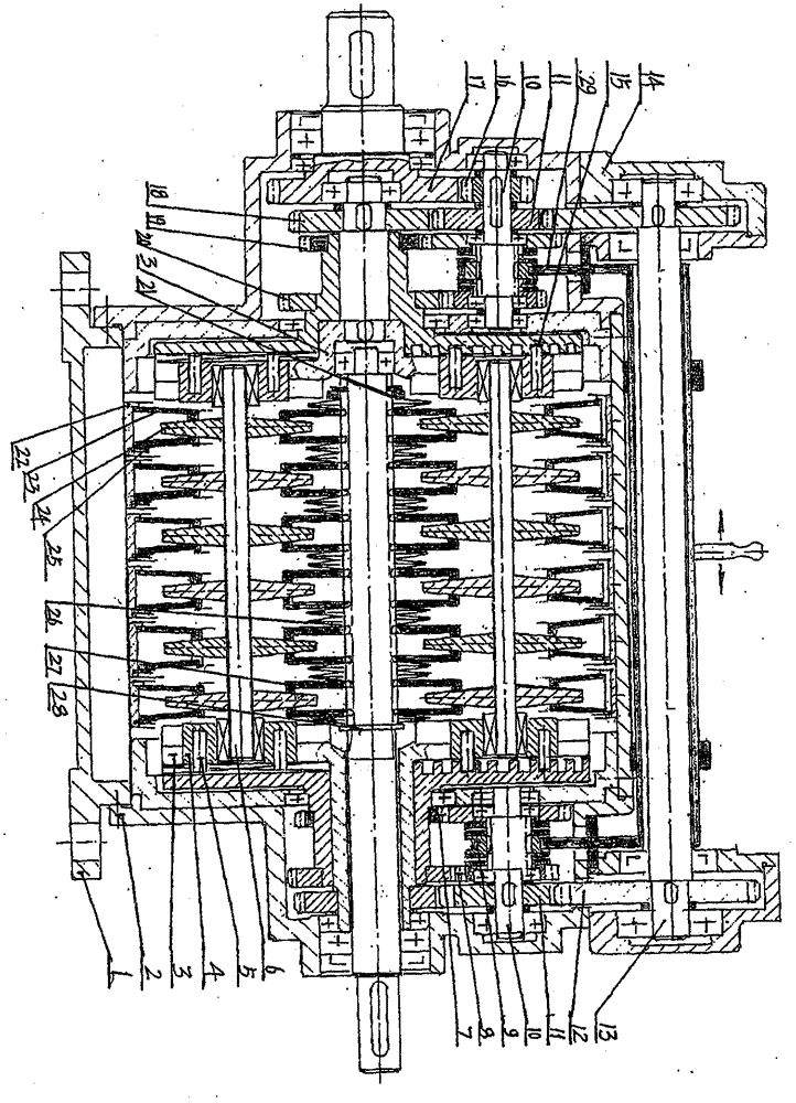
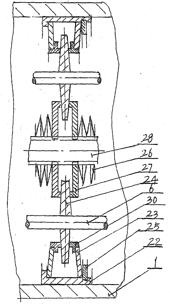
[0041] The best way to implement the present invention is described in detail according to the accompanying drawings, several pairs of driving wheels 27 are connected to the input spline shaft 28, and the planetary wheel 24 is clamped by the inner disc spring 26 on the outside, and the outer disc spring 23 and the outer pressure ring 30 are also Compressing the radial periphery of the planetary wheel 24, when the input spline shaft 28 drives the driving wheel 27 and the planetary wheel 24, the outer pressure ring 3C is clamped by the deformation elastic force of the outer disc spring 23, resulting in the deformation of the planetary wheel 24. Common rotation, each planetary gear 24 promotes small axle 6, slide block 4 rotating disk 3 and crankshaft 15 output torques.

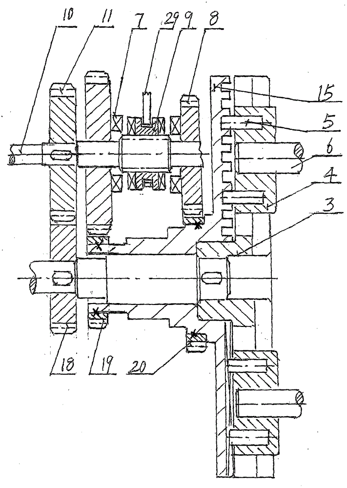
[0042] After the control puller 29 and the intermediate clutch 9 are combined with the grooved fifth gear or the sixth gear, through the transmission of the corresponding second gear or the third gear, because th...


PUM


Abstract

The invention relates to a radial roller screw and a variable-speed transmission thereof. A rotary disc (3), a toothed disc (15), a slide block (4) and a roller (5) are used for sheathing and rotation; when a differential gear is engaged by a clutch, the rotary disc (3) rotates relative to the toothed disc (15), the slide block (4) drives a small center shaft (6) and planetary wheels (24) to do radial displacement, the output rotation speed is gradually increased and decreased, and the stepless variable-speed transmission is realized; a spline shaft (28) is connected with a plurality of pairs of driving wheels (27) to respectively drive several planetary wheels (24); an outer press ring (30) and an outer disc spring (23) are fixedly connected and are arranged in a radial floating sleeve ring to form single-line transmission; the planetary wheels (24) are movably matched and parallelly connected with the small center shaft (6) to form a multi-line distribution beam type cage-shaped revolving body; the planetary wheels (24) are pressed by an inner disc spring and the outer disc spring, and the contact transmission force and torque are proportionally increased and decreased, and are consistently adjusted; the clutch (9) and a shift rod (29) synchronously move left and right at equal amount, and the small center shaft (6) parallelly displaces. Each line of planetary wheels (24) bears the load, so the contact stress is decreased, and the slip rate is reduced. The transmission effect of the high-power and high-efficiency stepless variable speed in automobiles and numerical control machining tools is obvious.

Description

technical field [0001] A speed change transmission mechanism with radial roller helix. The crankshaft with radial helical grooves and the turntable with radial sliding grooves fit together and rotate. The slider is installed in the chute of the turntable and driven by the rollers. Rolling connection into the radial helical socket of the tooth plate. When the crankset and the turntable rotate relative to each other, the helical alveolar angle on the crankset forces the rollers and sliders to move up and down in the chute of the turntable. Because a group of planetary gears are dynamically fitted on the small shaft through the shaft hole, the end of the small shaft is connected to the hole of the slide block and moves radially along with it, thereby realizing variable speed transmission. [0002] Several pairs of driving wheels are linked on the input spline shaft, and disc spring combinations are pressed against each other, so that each pair of driving wheels clamps several pl...

Claims


Application Information

Patent Timeline
Patent Type & Authority Patents(China)
IPC IPC(8): F16H37/02
CPCF16H37/02F16H2200/20
Inventor 陈驰川
Owner 南通弘铭机械科技有限公司
Why Eureka
Try Eureka