Field emission illumination device and method thereof

A light-emitting device, field emission technology, used in fluorescent screen lamps, lamp parts and other directions

Inactive Publication Date: 2014-12-17
张议聪
View PDF5 Cites 3 Cited by
  • Summary
  • Abstract
  • Description
  • Claims
  • Application Information

AI Technical Summary

Problems solved by technology

[0006] In view of the problems existing in the above-mentioned prior art, the object of the present invention is to provide a field em

Method used


Image

  • Field emission illumination device and method thereof
  • Field emission illumination device and method thereof
  • Field emission illumination device and method thereof

Examples


Embodiment Construction

[0022] In order to facilitate the understanding of the technical features, contents, advantages and the effects that can be achieved of the present invention, the present invention will be described in detail below in conjunction with the accompanying drawings and embodiments. The scope of protection claimed by the invention claims.

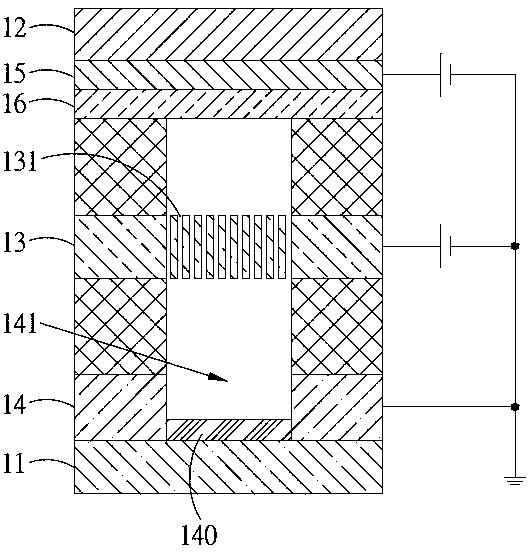
[0023] see figure 1 , which is a schematic diagram of the field emission light-emitting device proposed by the present invention. Such as figure 1 As shown, the field emission device proposed by the present invention includes a first substrate 11 , a second substrate 12 , a microchannel plate 13 , a grid layer 14 , an anode layer 15 and a fluorescent layer 16 . The second substrate 12 is disposed opposite to the first substrate 11 . The micro-channel plate 13 is disposed between the first substrate 11 and the second substrate 12 and has a plurality of electronic channels 131 . The gate layer 14 is disposed between the first substrate 11 and t...


PUM


Abstract

The invention discloses a field emission illumination device comprising a first substrate, a second substrate, a micro channel plate, a grid layer, a positive layer and a fluorescent layer. The micro channel plate is mounted between the first substrate and the second substrate; the grid layer is mounted between the first substrate and the micro channel plate and provided with a grapheme field emission assembly; the positive layer is mounted between the second substrate and the micro channel plate; and the fluorescent layer is mounted between the micro channel plate and the positive layer. With grapheme as an emission source, start voltage of the field can be reduced; and with the micro channel plate as an electronic multiplier pipe, when an electron passes through the micro channel plate, an axial electric field of the micro channel plate forces the electron to have a crash with the channel wall for a plurality of times, so electron numbers are multiplied.

Description

technical field [0001] The present invention relates to a field emission luminescent device and its method, in particular to a field emission luminescent device and its method which use graphene as a field emission source and increase current by means of a microchannel plate. Background technique [0002] The existing electron emission forms can be mainly divided into electron field emission (Electron field emission), thermionic emission (Electron thermionic emission), photoelectron emission (Photo electron emission) and secondary electron emission (Secondary electron emission), and the electron field emission The principle of launch is quite different from the other three. [0003] Among them, the principles of thermal electron emission, photoelectron emission and secondary electron emission all need to enable the internal electrons of the emitting object to obtain thermal energy, photon energy and secondary electron energy, so that they can obtain greater kinetic energy af...

Claims


Application Information

Patent Timeline
IPC IPC(8): H01J63/06H01J63/02
Inventor 张议聪王嘉圣池允中
Owner 张议聪
Why Eureka
Try Eureka