
Light source of high-capacity fiber Bragg grating sensing demodulating system

An optical fiber connection and optical amplifier technology, applied in the field of ring lasers, can solve problems such as low signal-to-noise ratio, loss, and inability to meet the requirements of signal detection and processing, and achieve the effect of stabilizing single-polarization lasers

Inactive Publication Date: 2014-12-17
中科融通物联科技无锡有限公司
View PDF3 Cites 4 Cited by
  • Summary
  • Abstract
  • Description
  • Claims
  • Application Information

AI Technical Summary

Problems solved by technology

[0003] Wide-spectrum light sources are generally composed of spontaneous emission spectrum emitted by SOA. When SOA is injected with 350mA current, the width of spontaneous emission spectrum is about 100nm, and the total power is less than 2mW. For F-P filter with fineness of 600 and FSR of 80nm The spectral width of the output spectrum is generally 0.13-0.16nm. In the region with a high spontaneous emission spectrum of SOA, the optical power allocated to each wavelength is only 20-30μW, and each wavelength allocated to multiple branches is only a few A μW is far from meeting the requirements of signal detection and processing; for a single-pumped EDFA, the power of the spontaneous emission spectrum is generally 30-50mW, the gain spectrum is 1530-1560nm, and the optical power allocated to each wavelength is only 40 -60μW, distributed to multiple branches, each wavelength is also at the μW level
In the fiber grating sensing project, if the traditional broadband light source is used, the optical power is small, and the power distributed to each grating after passing through the narrowband F-P filter is even smaller, so the signal-to-noise ratio of the system is not high. In actual engineering In the application, due to the long length of the channel fiber, there may be some losses, which will limit the system multiplexing capability, thereby limiting the scale of the system

Method used


Image

  • Light source of high-capacity fiber Bragg grating sensing demodulating system

Examples


Embodiment Construction

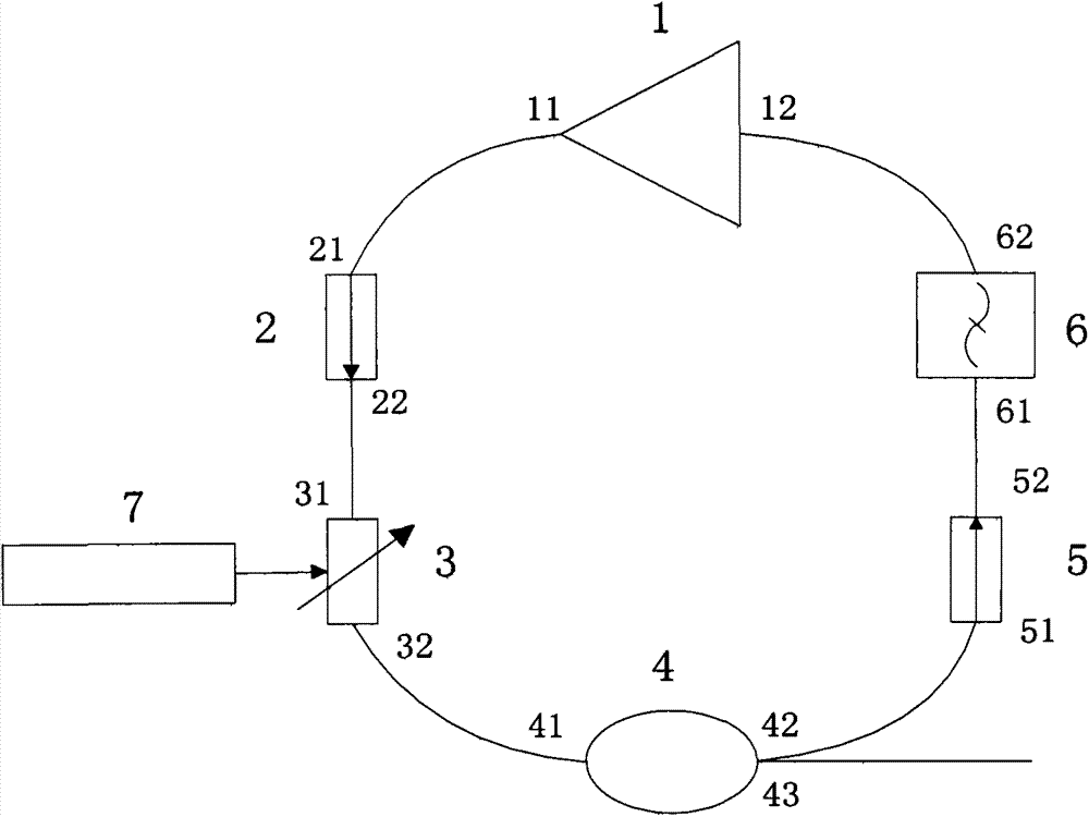
[0019] The present invention provides a kind of tunable ring laser, which is composed of semiconductor optical amplifier (SOA) 1, optical isolator 2, tunable F-P filter 3, splitting ratio is 1 × 2 optical coupler 4 of 40 / 60, optical isolation device 5, broadband filter 6, and piezoelectric ceramics 7. The coupler 4 is a three-port coupler with a first port 41 , a second port 42 and a third port 43 . The semiconductor optical amplifier output terminal 11 is connected to the optical isolator 2 through the optical fiber, and the optical isolator 2 is connected to the tunable F-P filter 3 through the optical fiber, and the tunable F-P filter 3 is connected to the 1×2 optical filter through the optical fiber. A port 41 of the coupler, two ports 42 of the 1×2 optical coupler are connected to the optical isolator 5 through an optical fiber, and the optical isolator 5 is connected to a broadband filter 6 through an optical fiber, and the broadband filter 6 passes The optical fiber is...


PUM

PropertyMeasurementUnit
Wavelengthaaaaaaaaaa

Abstract

The invention relates to a light source of a high-capacity fiber Bragg grating sensing demodulating system, in particular to a tunable circular laser comprising a semiconductor optical amplifier (SOA), two optical isolators, a broadband filter, a tunable F-P filter and a 1*2 optical coupler having a 40 / 60 splitting ratio. The output end of the semiconductor optical amplifier is connected to the first optical isolator through a fiber. The first optical isolator is connected to the tunable F-P filter through a fiber. The tunable F-P filter is connected to a first port of the 1*2 optical coupler through a fiber. A second port of the 1*2 optical coupler is connected to the second optical isolator through a fiber. The second optical fiber is connected to the broadband filter through a fiber. The broadband filter is connected to the input end of the semiconductor optical amplifier through a fiber. The 1*2 optical coupler outputs laser from the third port. The tunable circular laser is capable of outputting tunable circular fiber laser.

Description

technical field [0001] The invention relates to the technical fields of optical communication and optical fiber sensing, in particular to the application of a fiber laser as a light source in a fiber Bragg grating sensing system, that is, an SOA-based tunable ring laser. Background technique [0002] The ring cavity laser formed by using Semiconductor Optical Amplifier (Semiconductor Optical Amplifier, SOA) through optical fiber feedback has many unique advantages, such as high average output power, stable wavelength, and stable high repetition rate, making it suitable for optical fiber communication and all-round It is possible to obtain a wide range of potential applications in optical signal processing technology, especially in the field of optical sensing. [0003] Wide-spectrum light sources are generally composed of spontaneous emission spectrum emitted by SOA. When SOA is injected with 350mA current, the width of spontaneous emission spectrum is about 100nm, and the t...

Claims


Application Information

Patent Timeline
IPC IPC(8): H01S5/50H01S5/06
Inventor 王嵚王江孙福林
Owner 中科融通物联科技无锡有限公司
Learn More