System for removing exhaust gas samples from internal combustion engines

A technology for internal combustion engines and equipment, applied in sampling, sampling devices, engine testing, etc., to achieve the effects of reduced pressure loss, simple fixing and installation, and low pressure loss

Active Publication Date: 2014-12-17
AVL EMISSION TEST SYST GMBH
View PDF7 Cites 2 Cited by
  • Summary
  • Abstract
  • Description
  • Claims
  • Application Information

AI Technical Summary

Problems solved by technology

[0005] The technical problem underlying the present invention is therefore to develop a device that guarantees a representative sampling according to regulations by avoiding the formation of areas of poor exhaust gas mixing

Method used


Image

  • System for removing exhaust gas samples from internal combustion engines
  • System for removing exhaust gas samples from internal combustion engines

Examples


Embodiment Construction

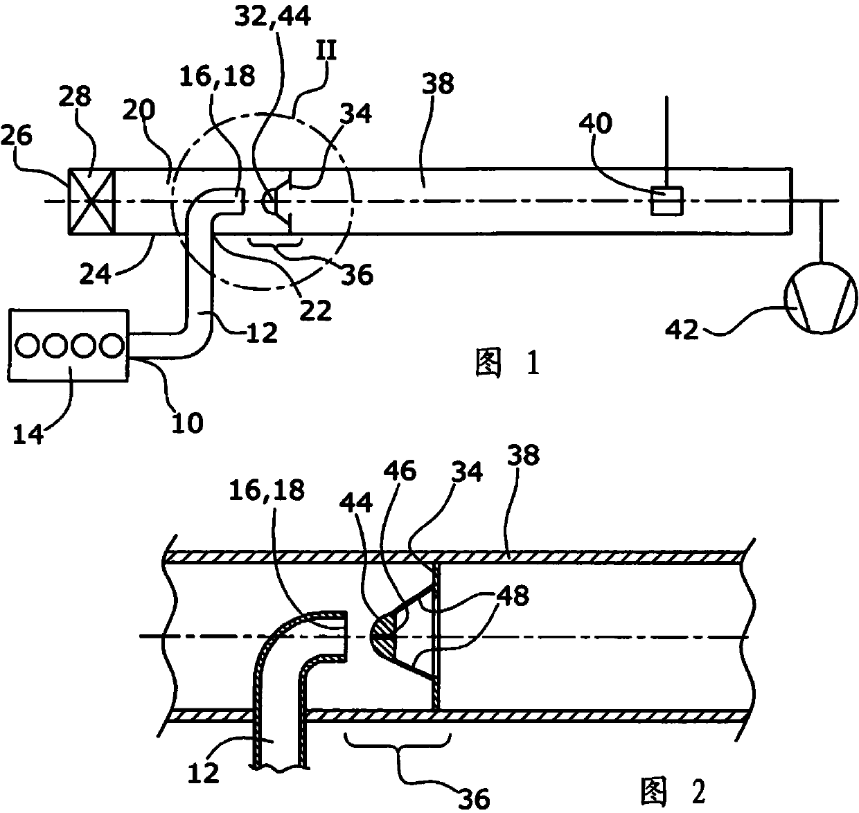
[0026] The device according to the invention for obtaining exhaust gas samples from an internal combustion engine of a diesel or gasoline engine comprises an exhaust gas inlet 10 through which an exhaust gas channel 12 is in fluid communication with an exhaust gas source 14 formed by the internal combustion engine of a vehicle.

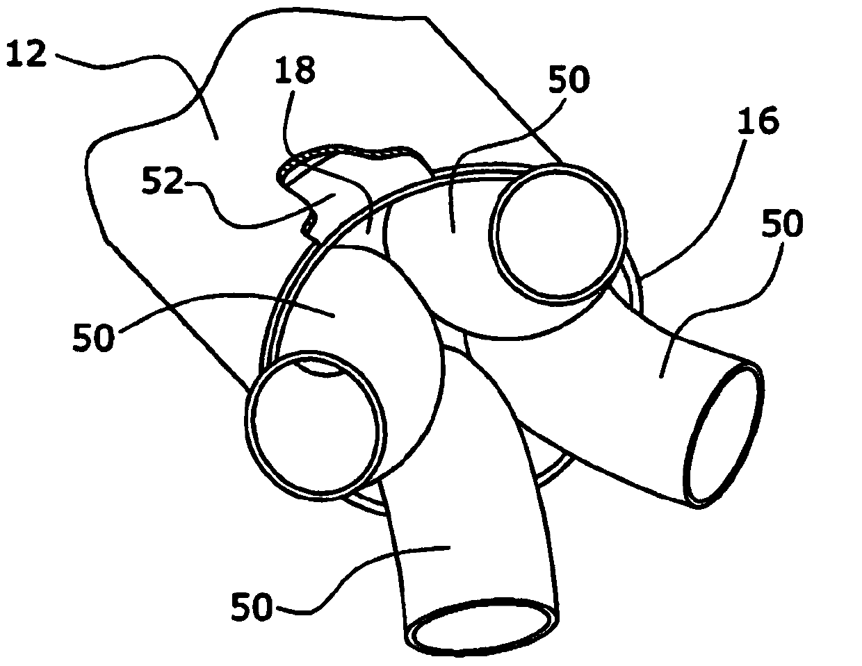
[0027] The exhaust gas channel 12 has an end 16 with an outflow cross section 18 which opens concentrically in an air channel 20 . For this purpose, this air channel 20 has in its boundary wall 24 an opening 22 through which the exhaust gas channel 12 protrudes vertically into the air channel 20 . In order to open concentrically in the air channel 20 , the exhaust gas channel 12 has a deflection of 90°.

[0028] Upstream of the flow of the exhaust gas channel 12, the air channel 20 has an inlet 26, on which a first air filter 28, usually formed by three filters, is arranged, through which air can be sucked into the Inside the air channel 20. The def...


PUM


Abstract

Systems for removing exhaust gas samples from internal combustion engines are know, said systems comprising: an exhaust gas duct (12) having fluid communication with an exhaust gas source (14) via an exhaust gas inlet (10); an air duct (20) into which ambient air can be suctioned via an air filter (28); a fusion zone (36) arranged downstream of an outflow cross section (18) of the exhaust gas duct (12); and a dilution tunnel (38), through which the exhaust gas / air mixture flows, wherein the outflow cross section (18) of the exhaust gas duct (12) is arranged substantially concentric in the air duct (20) and an annular orifice (34) is arranged downstream of the outflow cross section (18) of the exhaust gas duct (12) in the dilution tunnel (38). However, the two gas flows are often inadequately mixed. In order to ensure good mixing and representative sampling, the invention therefore proposes that means (32, 44, 50) are arranged upstream of the orifice (34) and downstream of the outflow cross section (18) of the exhaust gas channel (12), via which means the exhaust gas flow is deflected in such a manner that the exhaust gas flow is removed directly upstream of the means (32, 44, 50) and asymmetrically from the centre axis of the dilution tunnel (38).

Description

technical field [0001] The invention relates to a device for obtaining exhaust gas samples from an internal combustion engine, said device having an exhaust gas channel in fluid communication with an exhaust gas source via an exhaust gas inlet, in which an air channel through which ambient air can be sucked in through an air filter, arranged in the exhaust gas Mixing zone downstream of the outflow cross-section of the channel, dilution tunnel through which the exhaust gas-air mixture flows, wherein the outflow cross-section of the exhaust gas channel is arranged substantially concentrically with the air channel and downstream of the outflow cross-section of the exhaust gas channel in the dilution There is an annular baffle in the tunnel. Background technique [0002] Such devices are known, for example, from CVS devices (Constant Volume Sampling). In this device, exhaust gas is always mixed with air, so that a constant overall volume flow of the air-exhaust gas mixture resu...

Claims


Application Information

Patent Timeline
Patent Type & Authority Applications(China)
IPC IPC(8): G01N1/22
CPCG01N1/2252G01N33/0018G01N2001/2255G01M15/102
Inventor A.迪科R.巴利克S.威利克
Owner AVL EMISSION TEST SYST GMBH
Why Eureka
Try Eureka