An anti-nodulation device for furnace roll surface of strip steel annealing furnace

An annealing furnace and anti-nodulation technology, applied in furnaces, heat treatment furnaces, furnace types, etc., can solve the problems of increasing the consumption of spare parts, increasing the number of furnace openings, and replacing furnace rollers with high labor intensity, so as to improve product yield and The effect of the unit operation rate, the reduction of spare parts costs and production costs, and the reduction of the number of roll changes in the furnace

Active Publication Date: 2016-08-03
MAGANG (GROUP) HOLDING CO LTD +1
View PDF6 Cites 0 Cited by
  • Summary
  • Abstract
  • Description
  • Claims
  • Application Information

AI Technical Summary

Problems solved by technology

Because a small amount of iron oxide on the surface of the strip is reduced to sponge iron under the conditions of high temperature and reducing atmosphere, coupled with the speed difference between the strip and the furnace roll (the change of the speed of the unit and the speed difference of the inertial system of the steel belt) and the surface of the furnace roll Due to the roughness of the roller surface, the generated sponge iron is very easy to take root and grow at the valley point of the roller surface roughness. , affecting the quality of strip products
At present, the anti-nodulation device on the furnace roll surface of the strip steel annealing furnace has not been disclosed to solve the problem of nodulation on the furnace roll surface. Only the anti-nodulation DPC-74 (cermet) is used as the coating material for the furnace roll. The disadvantage is that the price of the coating material is high. Increase the production cost; or increase the number of times of furnace opening and replace the nodulation furnace roll. The disadvantage is that once the furnace is opened, the temperature will be lowered and then heated up, and the energy consumption will be large. Frequent furnace opening will affect the service life of the annealing furnace. Consumption of spare parts greatly increases production costs

Method used


Image

  • An anti-nodulation device for furnace roll surface of strip steel annealing furnace

Examples


Embodiment Construction

[0012] The present invention will be further described in detail below in conjunction with the embodiments.

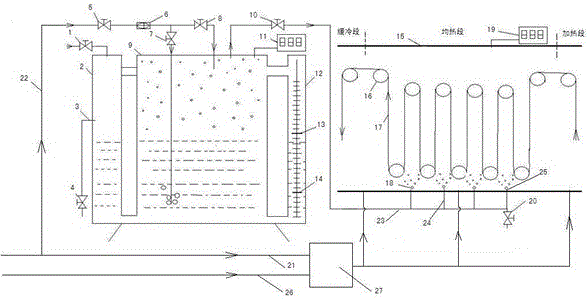
[0013] Depend on figure 1 It can be seen that an anti-nodulation device for the furnace roll surface of a strip steel annealing furnace comprises an annealing furnace 15, a furnace roll 16 is arranged in the annealing furnace, a furnace room dew point indicator 19 is arranged outside the top of the soaking section of the annealing furnace, and a nitrogen delivery pipe 21. The hydrogen delivery pipe 26 is respectively connected to the gas source and the gas mixing station 27, the gas mixing station supplies gas to the annealing furnace, the nitrogen delivery pipe is provided with an air intake pipeline 22, and the outlet end of the air intake pipeline is controlled by a nitrogen inlet valve 5, decompression Valve 6, moisture regulating valve 7, and dry gas regulating valve 8 are connected to the nitrogen humidification device, and the nitrogen humidification device is c...


PUM


Abstract

The utility model relates to an anti-nodulation device for a furnace roll surface of a strip steel annealing furnace, which belongs to strip steel heat treatment equipment, and in particular relates to a strip steel continuous annealing furnace. The characteristic is that the nitrogen delivery pipe is provided with an inlet pipeline, and the outlet end of the inlet pipeline is connected to a nitrogen humidification device by a nitrogen gas inlet valve, a pressure reducing valve, a moisture regulating valve, and a dry gas regulating valve, and the nitrogen humidification device is fed into the furnace by moisture. The regulating valve and the injection pipeline are connected to the wet gas nozzle at the bottom of the soaking section of the annealing furnace, and the air intake pipeline, the nitrogen humidification device, the injection pipeline and the annealing furnace form a gas passage. The advantage is that the dew point of the atmosphere in the soaking section of the annealing furnace of the device is -27°C to -35°C, and the gas particles with a high dew point are first enriched at the valley point of the roughness of the non-strip contact surface of the furnace roll, and the high temperature from the heating section The strip steel wraps it, and the gas particles expand when heated, which effectively prevents the sponge iron on the strip steel from sticking to the furnace rolls, improves product quality, reduces the number of times of furnace roll replacement, reduces spare parts costs and production costs, and improves product quality. Product yield and unit operating rate.

Description

technical field [0001] The invention belongs to strip steel heat treatment equipment, in particular to a strip steel continuous annealing furnace. Background technique [0002] The continuous annealing furnace is an important cold rolling annealing equipment. The currently used annealing furnace is equipped with a preheating section, a heating section, a soaking section, a slow cooling section, a fast cooling section, an overaging section, a secondary cooling section and a final cooling section. The soaking section of the closed furnace chamber is filled with nitrogen-hydrogen mixed gas with a dew point of -40°C to -50°C. The strip steel at normal temperature enters the furnace and is preheated and heated continuously in the heating section. The surface temperature of the strip steel in the soaking section reaches as high as 680°C to 850°C, and lasts for 44s to 109s in the soaking section. Because a small amount of iron oxide on the surface of the strip is reduced to sponge...

Claims


Application Information

Patent Timeline
Patent Type & Authority Patents(China)
IPC IPC(8): C21D9/56C21D1/74C21D1/26
Inventor 王德瑶许翔
Owner MAGANG (GROUP) HOLDING CO LTD
Why Eureka
Try Eureka