
An electric control valve and its control system

A valve control system and valve technology, applied in the direction of engine control, output power, machine/engine, etc., can solve the problems of inaccurate control of valve lift and opening time, complex engine structure, low fuel utilization rate, etc., and achieve simple structure , Full combustion, high precision effect

Active Publication Date: 2017-06-13
何权
View PDF12 Cites 2 Cited by
  • Summary
  • Abstract
  • Description
  • Claims
  • Application Information

AI Technical Summary

Problems solved by technology

Such a setting makes the structure of the engine complex, and the lift and opening time of the valve cannot be accurately controlled, and the sensitivity is low. When the car runs at a lower speed, it may cause insufficient air intake in the cylinder, resulting in low fuel utilization.

Method used


Image

  • An electric control valve and its control system
  • An electric control valve and its control system
  • An electric control valve and its control system

Examples


Embodiment Construction

[0020] The present invention will be described in further detail below through specific implementation examples and in conjunction with the accompanying drawings.

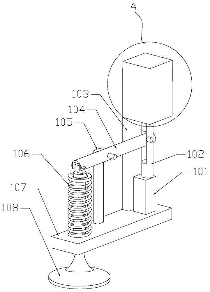
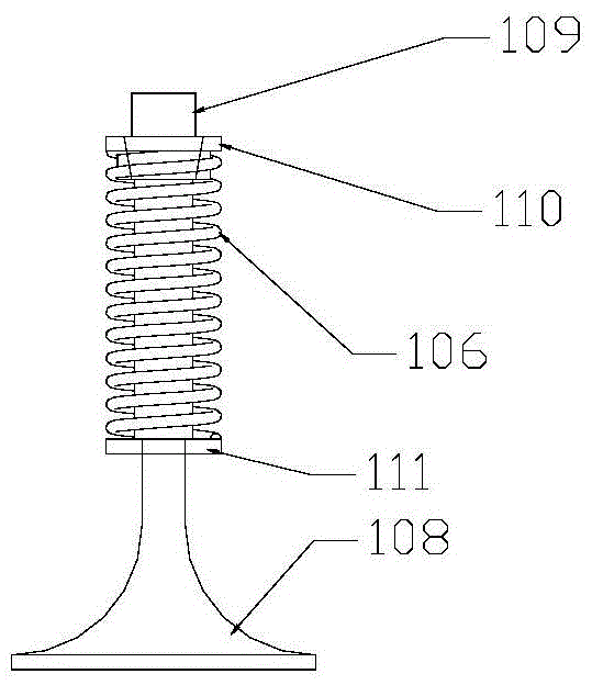
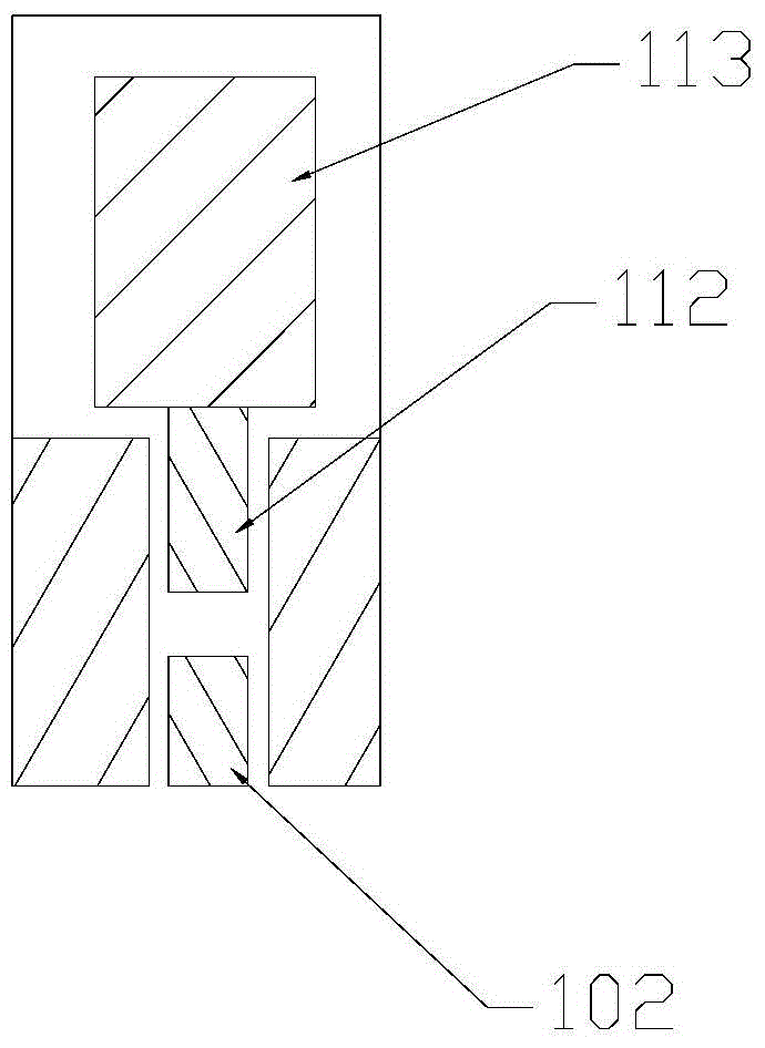
[0021] refer to Figure 1-3 , the electronically controlled valve provided by the embodiment of the present invention includes a valve group, a solenoid valve 101, a lever assembly and a motor controlled by a pulse signal. The lever assembly includes a rotating rod 104 and a rotating rod support 105 , and the rotating rod 104 is rotatably connected to the rotating rod support 105 . The solenoid valve 101 includes a vertically displaceable spool 102 , the spool 102 is rotatably connected to one end of the rotating rod 104 and drives the rotating rod 104 to generate vertical displacement. The valve group includes a connected valve 108 and a valve rod 109, the rotating rod support 105 is arranged between the valve rod 109 and the valve core 102, the other end of the rotating rod 104 is connected to the valve The rod...


PUM


Abstract

The invention provides an electronically controlled valve and an electronically controlled valve control system. The electronically controlled valve includes a valve group, a solenoid valve, a lever assembly and a motor controlled by a pulse signal; the lever assembly includes a rotating rod and a rotating rod support, and the electromagnetic valve includes Vertically displaceable, the valve group includes connected valves and valve stems, the motor controlled by the pulse signal includes a motor shaft, and an adjustable gap is arranged between the valve core and the motor shaft. The electronically controlled valve control system includes electronically controlled valve, air flow meter, throttle sensor, crankshaft position sensor and engine electronic control unit. The engine electronic control unit sends signals according to the signals transmitted by the air flow meter, throttle sensor, and crankshaft position sensor to control the movement of the spool and the motor shaft, thereby controlling the lift and opening and closing of the valve, and then accurately controlling the intake air volume and The amount of fuel injected not only ensures the efficiency of the engine but also improves the fuel utilization rate of the engine.

Description

technical field [0001] The invention relates to the field of automobile engines, in particular to an electronically controlled valve and a control system thereof. Background technique [0002] The commonly used valve mechanism now includes a valve group, a rocker arm and a camshaft with an eccentric cam. The valve group is connected to the rocker arm. Compress the valve group to move the valve group down to realize the opening of the valve. Such a setting makes the structure of the engine complex, and the lift and opening time of the valve cannot be accurately controlled, and the sensitivity is low. When the car is running at a low speed, the intake air in the cylinder may not be sufficient, resulting in low fuel utilization. Contents of the invention [0003] The object of the present invention is to provide an electronically controlled valve and an electronically controlled valve control system to improve the control precision of the valve lift. [0004] The present in...

Claims


Application Information

Patent Timeline
Patent Type & Authority Patents(China)
IPC IPC(8): F02D13/02
Inventor 何权
Owner 何权
Learn More