Method and device for temperature control of hydraulic oil tank

A technology of temperature control device and hydraulic oil tank, applied in the direction of fluid pressure actuation device, fluid pressure actuation system components, mechanical equipment, etc., can solve the problem of poor on-site temperature control effect, etc. Precise control and reduce labor intensity

Active Publication Date: 2017-06-23
SHANGHAI MEISHAN IRON & STEEL CO LTD
View PDF1 Cites 0 Cited by
  • Summary
  • Abstract
  • Description
  • Claims
  • Application Information

AI Technical Summary

Problems solved by technology

[0003] The present invention aims at the technical problems existing in the prior art, and provides a method and device for controlling the temperature of the hydraulic oil tank, which mainly solves the technical problem of poor on-site temperature control effect existing in the existing temperature control device

Method used


Image

  • Method and device for temperature control of hydraulic oil tank
  • Method and device for temperature control of hydraulic oil tank
  • Method and device for temperature control of hydraulic oil tank

Examples


Embodiment 1

[0032] Embodiment 1: A hydraulic oil tank temperature control device, the temperature control device includes a temperature detection unit, a temperature processing unit and an execution unit, wherein the temperature detection unit transmits the detection data to the temperature processing unit, and the temperature processing unit transmits the processed execution command to the execution unit.

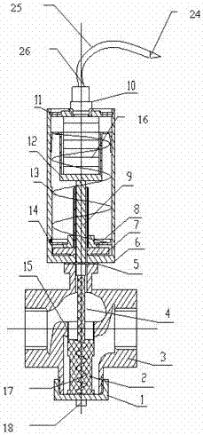
[0033] The temperature detection unit includes a probe 24, a connecting nut, a transfer pipe 25, a damping ring, and a protection spring 27, wherein the probe 24 is arranged on the head of the detection unit, and is connected with the transfer pipe 25 by welding, and the afterbody of the probe can be installed with The connecting nut is provided with a step, a sealing groove is placed on the step, and a lock nut is arranged on the outside of the step, so that it is not directly inserted into the fuel tank but is threaded at the part closest to the inlet circulation pipe of the cooler; ...

Embodiment 2

[0034] Example 2: see image 3 , Figure 4 , Figure 5-1 , Figure 5-2 , Figure 6 , Figure 7-1 , Figure 7-2 , as an improvement of the present invention, the temperature processing unit includes a force feedback alloy stack spring 16, a first support guide block 12, a pressure setting spring 13, a force transmission guide rod 9, a second support guide block 14, a support adjustment Round nut 8, adjusting stud 28, adjusting handle 7;

[0035] The force feedback alloy stack spring 16 is a force feedback element that rapidly expands or compresses proportionally through the detected temperature, the first support guide block 12, the pressure setting spring 13, the second support guide block 14, and the support adjustment The round nut 8, the adjusting stud 28, and the adjusting handle 7 form an initial pressure setting mechanism; by rotating the adjusting handle 7, the elastic force of the pressure setting spring 13 is overcome, and the adjusting stud 28 is driven to move...

Embodiment 3

[0037] Embodiment 3: see figure 2 , image 3 , as an improvement of the present invention, the adjustment handle 7 is provided with a concave-convex platform that is highly centered with the bottom of the outer cover and an octagonal structure that facilitates the adjustment of the pressure setting spring in a narrow space, and the opening between the structures is smaller than the opening of the outer cover Portion size.


PUM


Abstract

The invention relates to a hydraulic oil tank temperature control device, characterized in that the temperature control device includes a temperature detection unit, a temperature processing unit and an execution unit, wherein the temperature detection unit transmits the detected data to the temperature processing unit, and the temperature processing unit processes the The execution command is passed to the execution unit. The beneficial effects of the present invention are as follows: the head of the receiving unit in the device of the present invention is directly in contact with the oil, so that the oil temperature can be quickly and accurately transmitted to the force conversion part of the processing element, and then the oil tank can be easily moved The temperature is effectively controlled at 40°. The device of the present invention is force-balanced, has better follow-up performance, and can achieve the expected goal; secondly, the present invention installs the detection part in the hydraulic oil, and the control device is installed on the circulating cooling water pipe, and the two do not interfere with each other. The force feedback makes the oil temperature well controlled.

Description

technical field [0001] The present invention relates to a method and a device for controlling the temperature of an oil tank, in particular to a method and a device for controlling the temperature of a hydraulic oil tank. Specifically, the temperature of the hydraulic oil tank is automatically adjusted and the flow rate of the medium water passing through the valve body is controlled to control the oil temperature. Warming method and apparatus. Background technique [0002] The hydraulic system is widely used in iron and steel enterprises. With the continuous development of science and technology and the continuous improvement of plate requirements, a large number of hydraulic proportional servo systems are used in the hydraulic system. If you want to roll out products with higher precision, you must The performance of the proportional servo valve must be guaranteed. Since the temperature of the hydraulic oil has a significant impact on the flow response characteristics of t...

Claims


Application Information

Patent Timeline
Patent Type & Authority Patents(China)
IPC IPC(8): F15B21/04
Inventor 王金华严加根
Owner SHANGHAI MEISHAN IRON & STEEL CO LTD
Why Eureka
Try Eureka