Backflow blocking valve

A backflow and valve body technology, applied in the field of check valves and valves, can solve the problems of inability to provide valve mold blanks, large check valve valve bodies, and expensive models, so as to facilitate the selection of new models and replacement of damaged valves. Quick, simple-to-build effects

Inactive Publication Date: 2014-12-24
黄健山
View PDF5 Cites 6 Cited by
  • Summary
  • Abstract
  • Description
  • Claims
  • Application Information

AI Technical Summary

Problems solved by technology

[0005] 2. The basic valve body of the check valve with the speed control technology of the spool is thick, the deconstruction is complicated, the manufacturing process is many and it is not easy to repair
[0007] As we all know, most valves are cast, and the casting process of various metals is different, and the carriers required to transport various fluid media are also different, for example: seawater must use stainless steel 316 valve pipes , hot water is suitable for copper valve pipes, but since most of the valves are cast, further:
[0008] 1: The casting process determines the material it produces, and then the material limits the medium it can carry, (for example: a factory has a cast iron production line, although the process is very complete, it cannot provide stainless steel or copper valves with the same shape Die blanks, so stainless steel or copper valves for seawater or hot water cannot be produced)
[0009] 2: The molding form limits the size of the valve shape. Casting and punching are inseparable from the model. The size of the model is fixed, and the model is expensive. Normally, there will be no manufacturers with the same structure to make models of various lengths. (For example, you have taken a fancy to the structure of a certain valve manufacturing company, and the material that the valve can provide is also suitable, but the size of the valve that can be provided by this type of valve of this factory is fixed due to the model relationship, and its length cannot meet the needs of users ),

Method used


Image

  • Backflow blocking valve
  • Backflow blocking valve
  • Backflow blocking valve

Examples


Embodiment 1

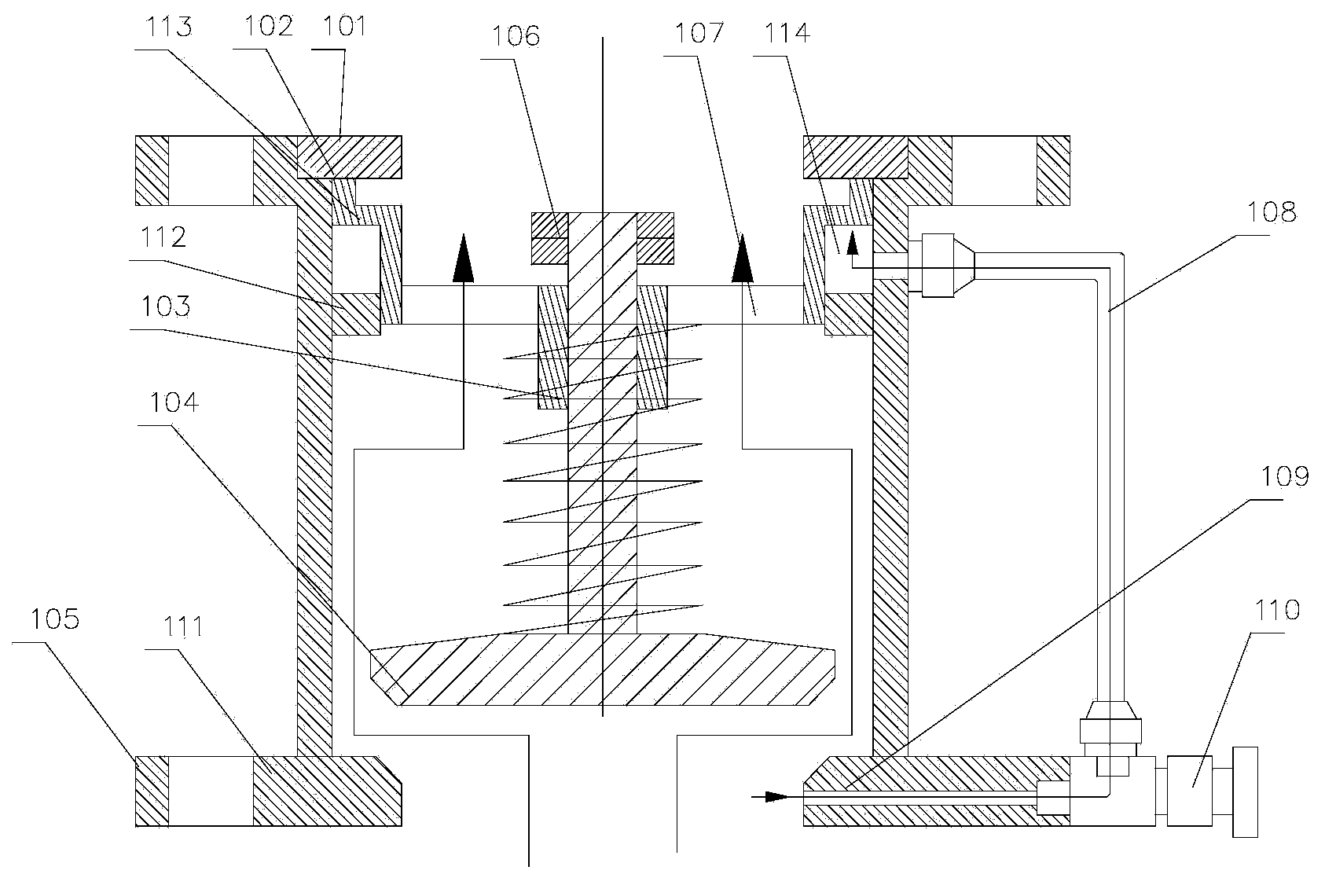
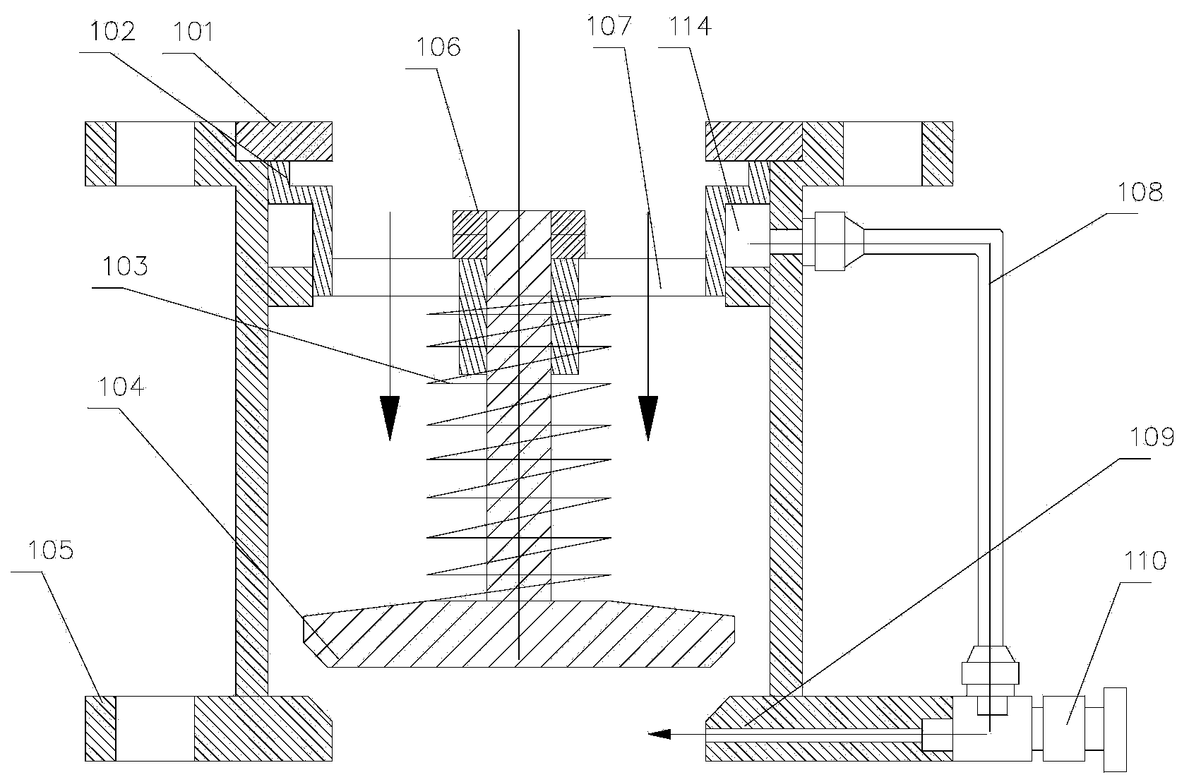
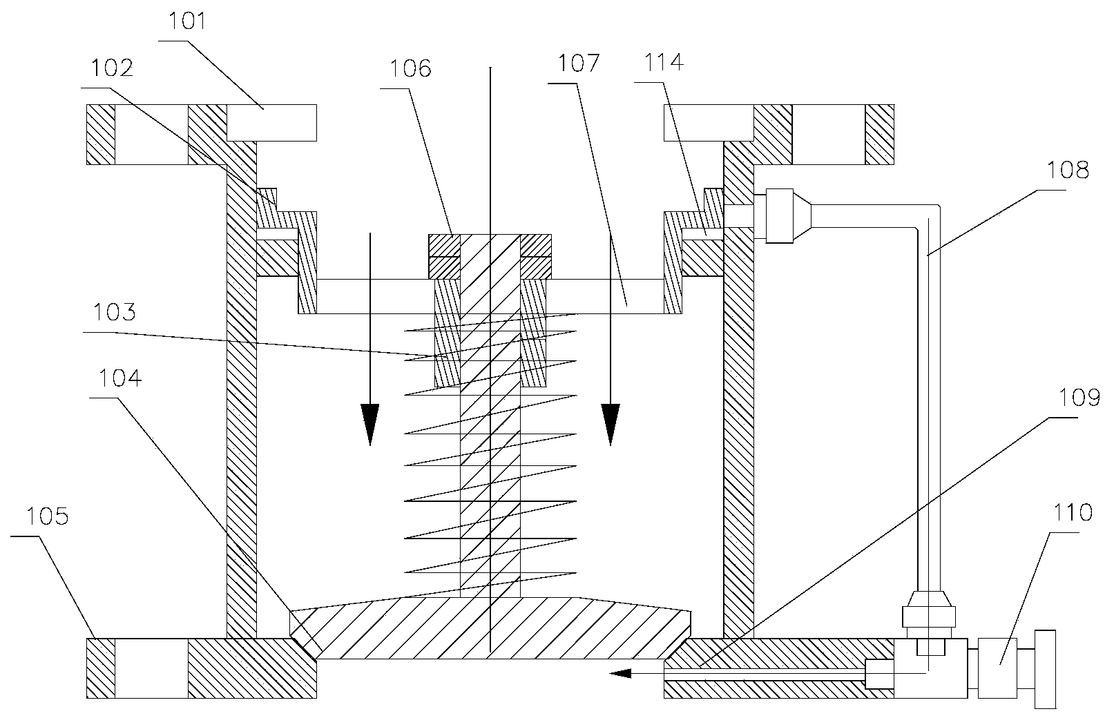
[0047] Such as Figure 1~3 Shown is an embodiment of the backflow prevention valve of the present invention. As a basic form, it includes a valve body 105, the inside of which is a valve cavity that can accommodate fluid, and the valve body 105 has a first limit end in the liquid inlet direction and a second limit end in the liquid outlet direction , the main body of the valve cavity formed between the first limiting end and the second limiting end is equipped with an auxiliary piston 102, a valve stem and a stopper that can slide in the axial direction, and the auxiliary piston 102 is connected with the valve inner cavity There is a liquid storage space between the walls that can accommodate the fluid to be delivered. When liquid is injected into the liquid storage space, the volume of the liquid storage space will increase due to the increase in pressure. On the contrary, the volume will decrease. When the volume of the liquid storage space When increasing, the auxiliary pi...

Embodiment 2

[0055] Such as Figure 4~6 Shown is another embodiment of the backflow prevention valve of the present invention. As a basic form, it includes a valve body 205, the inside of which is a valve cavity that can accommodate fluid, and the valve body 205 has a first limit end in the liquid inlet direction and a second limit end in the liquid outlet direction , the main body of the valve cavity formed between the first limit end and the second limit end is equipped with an auxiliary piston 202, a valve stem 209 and a stopper that can slide in the axial direction, and the auxiliary piston and the inner cavity of the valve Between the walls there is a reservoir space 214 which can contain the fluid to be delivered. When the volume of the liquid storage space increases, the auxiliary piston is in the open position due to the pressure of the liquid in the liquid storage space, and when the volume of the liquid storage space decreases, the auxiliary piston is in the closed state due to ...

Embodiment 3

[0061] Such as Figure 7-9 Shown is another embodiment of the backflow prevention valve of the present invention. As a basic form, it includes a valve body 305, inside the valve body is a valve cavity that can accommodate fluid, and the valve body 305 has a first limit end in the liquid inlet direction and a second limit end in the liquid outlet direction , the main body of the valve cavity formed between the first limit end and the second limit end is equipped with an auxiliary piston 302, a valve stem 309 and a stopper that can slide in the axial direction, and the auxiliary piston and the inner cavity of the valve body Between the walls there is a reservoir space 314 which can accommodate the fluid to be delivered. When the volume of the liquid storage space increases, the auxiliary piston is in the open position due to the pressure of the liquid in the liquid storage space, and when the volume of the liquid storage space decreases, the auxiliary piston is in the closed po...


PUM


Abstract

The invention discloses a backflow blocking valve. A valve body is provided with a first limit end located in the liquid inlet direction and a second limit end located in the liquid outlet direction; an auxiliary piston, a valve rod and a backstop part which are capable of sliding along the axial direction of a valve cavity are arranged in a valve cavity body formed between the first limit end and the second limit end; a liquid storage space is formed between the outer side wall of the auxiliary piston and the inner cavity wall of the valve body; when the pressure of liquid conveyed from a liquid inlet end is increased, the backstop part is opened by washing, and a fluid passes through a main flow channel of the auxiliary piston; when the pressure of the liquid conveyed from the liquid inlet end is decreased or disappears, the valve is closed in two steps, the backstop part is quickly returned toward the direction of the first limit end, the auxiliary piston is gradually returned, and the auxiliary piston, the backstop part and the first limit end jointly act to intercept liquid backflows coming from the liquid outlet direction when the auxiliary piston is returned to a close position. The valve manufacturing process is not limited by materials and overall dimensions, and is wide in application range.

Description

technical field [0001] The invention relates to the field of valves, in particular to the technical field of check valves. Background technique [0002] The check valve is an indispensable component in the pressure transmission pipeline. Its main function is to maintain the pressure at the outlet end when the pressure of the medium that has passed through the water (liquid) end decreases or disappears, so as to prevent the medium from flowing back and save energy. For energy and other purposes, with the increasing use of modern pipeline transportation, the medium pressure and flow rate are getting higher and higher, and the technical requirements for check valves are getting higher and higher. The number of times the spool moves, the moving speed and the force it carries during operation) are more vulnerable than other valves. There are many and miscellaneous models of manufacturers on the market, with different lengths, and it is very inconvenient to replace. [0003] In t...

Claims


Application Information

Patent Timeline
Patent Type & Authority Applications(China)
IPC IPC(8): F16K15/06
CPCF16K15/06
Inventor 黄健山
Owner 黄健山
Why Eureka
Try Eureka