Energy-efficient heat supply furnace
A high-efficiency energy-saving heating furnace technology, which is applied to furnaces/stoves with hot water devices, household heating, heating systems, etc., can solve problems such as low heat utilization rate, insufficient fuel combustion, and waste of fuel. Achieve the effects of reducing the generation of waste residue, improving the utilization rate of heat energy, and improving the utilization rate of heat
- Summary
- Abstract
- Description
- Claims
- Application Information
AI Technical Summary
Problems solved by technology
Method used
Image

Examples
Embodiment Construction
[0023] Below in conjunction with accompanying drawing embodiment, the present invention will be further described:
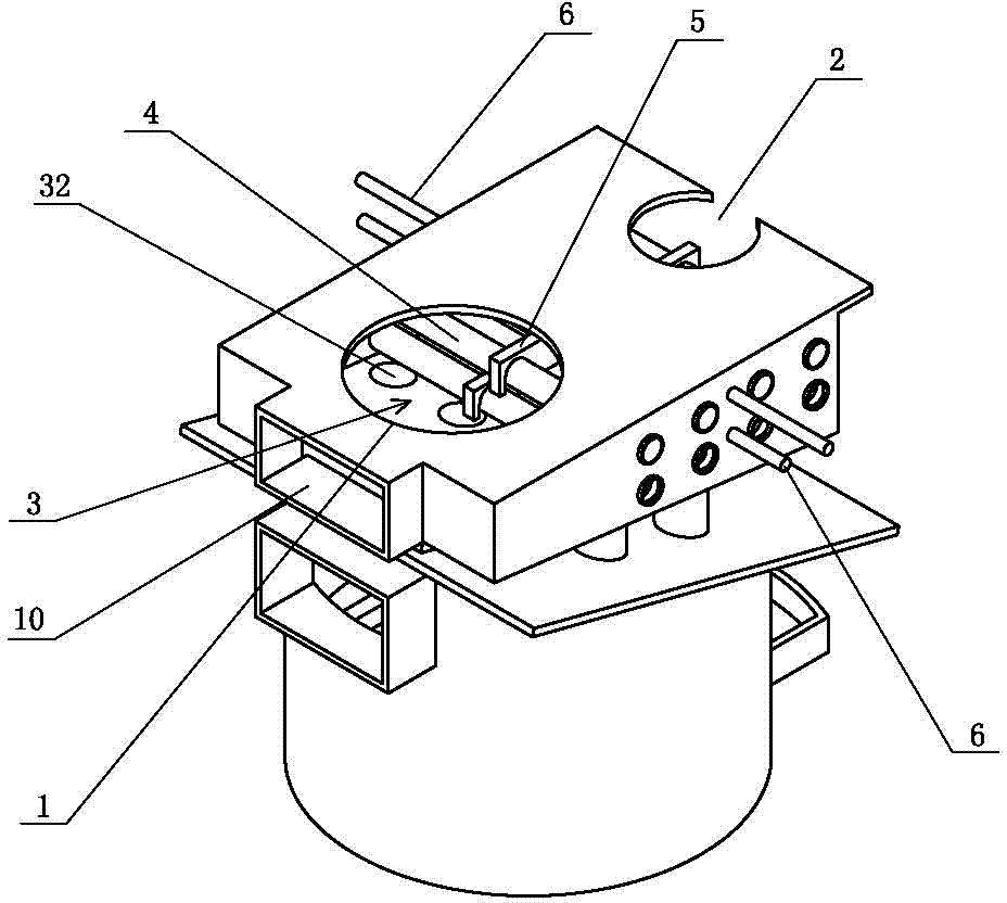
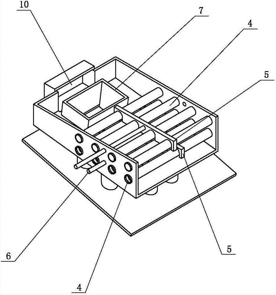
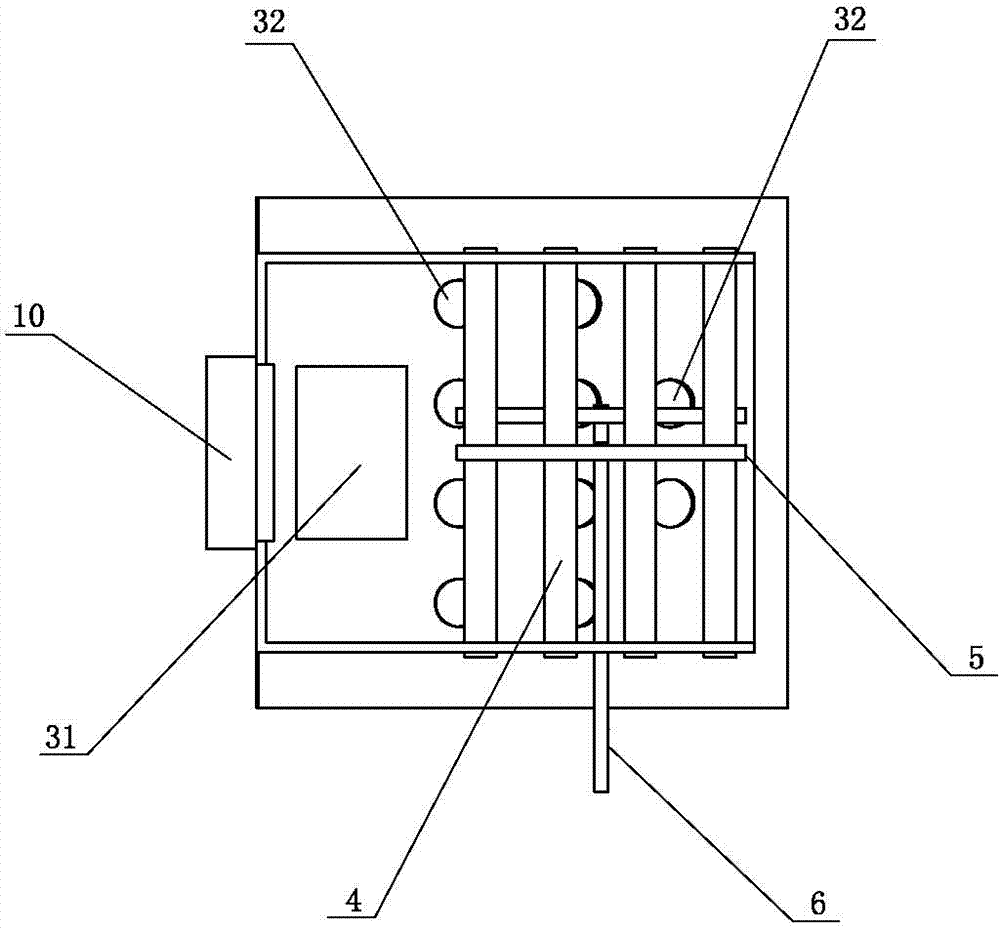
[0024] like Figures 1 to 6 As shown, a high-efficiency and energy-saving heating furnace includes a furnace body. One end of the furnace body top is provided with a stove port 1, and the other end is provided with a chimney connection port 2; It is a hollow closed water tank, located on the furnace 3 and below the stove mouth 1, and the main fire outlet 31 is set; on the upper part of the furnace 3, it runs through the peripheral wall of the furnace body in a horizontal direction, and there are two rows of warm water pipes 4, each of which are arranged in parallel. A dust-sweeping board 5 is all buckled on every row of warm water pipes 4; the bottom of the dust-sweeping board 5 is provided with four semicircular openings side by side at intervals, and these four openings are just stuck in four warm water pipes 4 tops, so that the dust-sweeping boards 5 can mov...
PUM
 Abstract
Description
Claims
Application Information
PatSnap Eureka turns technology decisions into work you can execute. Powered by our Innovation Knowledge Graph, it runs expert workflows across engineering, life sciences, materials and intellectual property. Get your review-ready output in minutes.


