Electric power conversion system equipped with electric storage device

A power conversion device and technology for power conversion, applied in the field of power conversion devices for power storage devices and DC-DC conversion devices, can solve problems such as reduced charging efficiency, damage to switching elements in DC-DC conversion circuits, and difficulty in removing capacitors, etc., to achieve The effect of preventing phase imbalance and reducing the number of units

Active Publication Date: 2014-12-24
HITACHI LTD
View PDF5 Cites 2 Cited by
  • Summary
  • Abstract
  • Description
  • Claims
  • Application Information

AI Technical Summary

Problems solved by technology

[0019] On the other hand, as shown in Patent Document 2, if the DC part on the side where the DC-DC conversion circuit is connected to the inverter circuit is configured without a capacitor connected in parallel at the nearest point, the DC-DC The surge voltage generated when switching the conversion circuit becomes too large due to the influence of wiring inductance, and the switching elements of the DC-DC conversion circuit may be destroyed
Therefore, when the inverter circuit and the DC-DC conversion circuit are connected by wires through different units, it is difficult to remove the capacitor connected in parallel with the DC-DC conversion circuit.
[0020] Furthermore, if the bus bar is divided as shown in Patent Document 3, the wiring inductance increases due to the influence of the length of the wiring from the bus bar to the capacitor. There is a difference between the phases in the distance up to the extraction position of the power supply electrode, so the inductance of the circuit is different between the phases, and it is related to the surge voltage and the imbalance of the load current when switching between the phases.
[0021] Second, the capacitor in the power conversion device has a large volume and weight, and it is not preferable to increase the number of capacitors excessively due to the constraints of the assembly under the vehicle floor, etc.
In addition, in the case of using a system in which an external power supply facility is used to charge the power storage device, the charging efficiency may decrease and stable control may become difficult.

Method used


Image

  • Electric power conversion system equipped with electric storage device
  • Electric power conversion system equipped with electric storage device
  • Electric power conversion system equipped with electric storage device

Examples


Embodiment 1

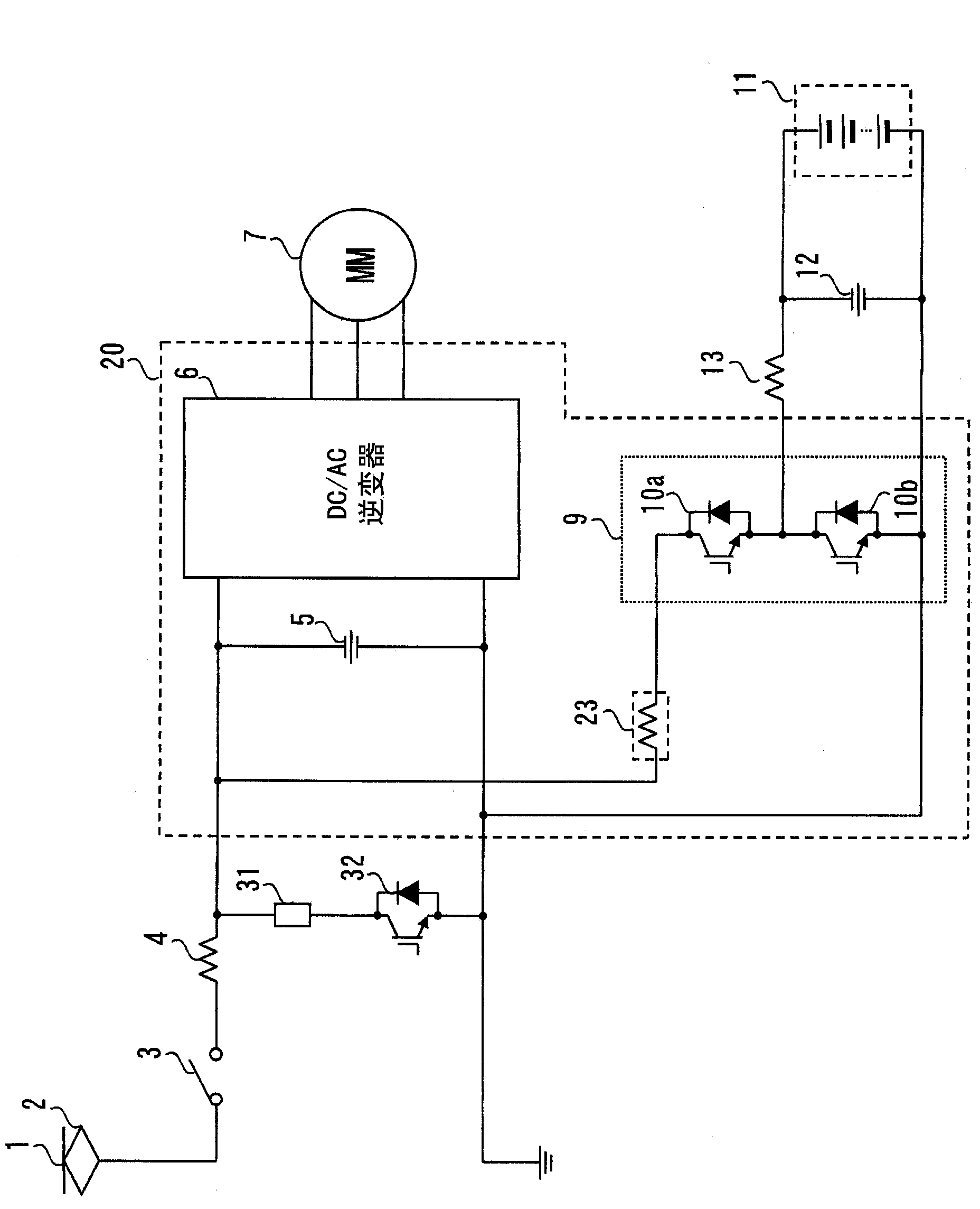
[0042] figure 1 It is a diagram showing a configuration example of a main circuit of a power conversion device according to Embodiment 1 of the present invention.

[0043] exist figure 1 In the power conversion device, 1 is a DC tram line, 2 is a power collector, 3 is a contactor, 4 is a reactor, 20 is an integrated unit of an inverter circuit 6 and a DC-DC conversion circuit 9, 7 is a motor, 11 is an electric storage device, 12 is a capacitor connected in parallel to the electric storage device 11, and 13 is a reactor. In the integrated unit 20 of the inverter circuit 6 and the DC-DC conversion circuit 9 (in the drawing, a portion surrounded by a dotted frame), 5 is a capacitor, and 10a, 10b are switching elements for performing DC-DC conversion. In addition, the inductance included in the wiring of the inverter circuit 6 and the DC-DC conversion circuit 9 is shown as a wiring inductance 23. 31 is a resistor, 32 is a switching element, and constitutes a discharge for disc...

Embodiment 2

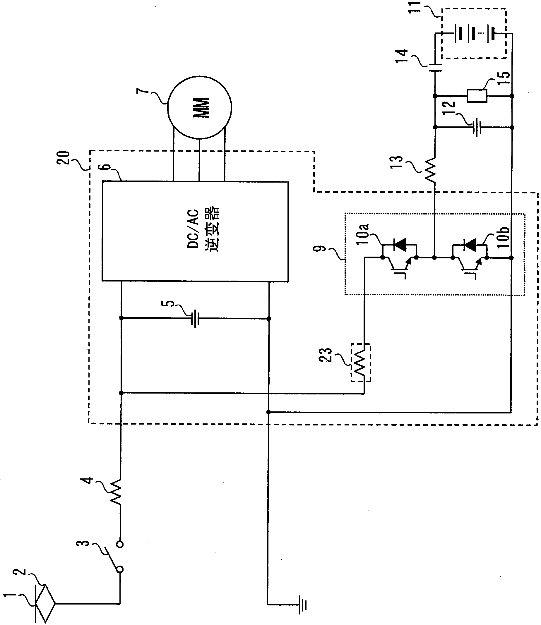
[0056] image 3 It is a diagram showing a configuration example of a main circuit of a power conversion device according to Embodiment 2 of the present invention.

[0057] exist image 3 In the power conversion device, the following description is related to figure 1 The different parts of the composition shown in Example 1.

[0058] image 3 Among them, a circuit breaker 14 is provided in series with the power storage device 11 on the side connecting the capacitor 12 and the power storage device 11 , and a resistor 15 is provided in parallel with the capacitor 12 . Further, omitted figure 1 The shown discharge circuit is composed of a resistor 31 and a switching element 32 .

[0059] With this circuit configuration, when it is desired to discharge the capacitor 5 in the integrated unit 20 , after the circuit breaker 14 is opened, the switching element 10 a on the upper arm side in the DC-DC conversion circuit 9 is turned on. Thus, a closed circuit passing through the ...

Embodiment 3

[0062] Figure 4 It is a diagram showing a configuration example of a main circuit of a power conversion device according to Embodiment 3 of the present invention.

[0063] exist Figure 4 In the power conversion device, the following description is related to figure 1 The different parts of the composition shown in Example 1.

[0064] compared to figure 1 In the shown circuit configuration, in this configuration, a series circuit of a resistor 31 and a switching element 32 is provided in parallel with the capacitor 5 in an integrated unit 20 including the inverter circuit 6 and the DC-DC conversion circuit 9 of the capacitor 5 .

[0065] The series circuit of the resistor 31 and the switching element 32 is a discharge circuit for discharging the capacitor 5 and the capacitor 12 . By mounting this discharge circuit in an integrated unit 20 including the inverter 6 and the DC-DC conversion circuit 9 of the capacitor 5, the wiring inductance up to the discharge circuit can...


PUM


Abstract

The invention provides an electric power conversion system equipped with electric storage device. To suppress resonance operation in a DC unit to which an inverter circuit and a DC-DC converting circuit are connected, a surge voltage generated upon switching of the DC-DC converting circuit and unbalance of load current between phases, and, furthermore, to realize stable control of the inverter circuit and the DC-DC converting circuit. By configuring the inverter circuit and the DC-DC converting circuit which configure an electric power conversion system within the same unit along with a shared capacitor at a DC input side, variation in wiring inductance between the inverter circuit and the DC-DC converting circuit and circuit inductance between the phases is reduced.

Description

technical field [0001] The present invention relates to a system configuration of a power conversion device equipped with a power storage device, and in particular, to an inverter device that converts direct current into alternating current, is connected in parallel to the inverter device, and converts a first direct current voltage into a second direct current. A DC-DC conversion device for voltage and a method for configuring a power conversion device for an electric storage device. Background technique [0002] Among inverter devices widely used in the industry, a method of converting DC power into AC power by variable voltage variable frequency (VVVF) control using a pulse width modulation (PWM) method is widely used. [0003] For example, in the field of railway vehicles, regenerative braking control is widely used, that is, by using a VVVF inverter device to drive a motor to accelerate the vehicle, and by operating the motor as a generator during braking to convert kin...

Claims


Application Information

Patent Timeline
Patent Type & Authority Applications(China)
IPC IPC(8): H02M7/48
CPCH02M7/48H02M7/003Y02T10/7072Y02T90/14B60L50/53B60L53/24Y02T10/70B60L7/16B60L9/22H02H7/1213H02M1/36H02M1/322
Inventor 筱宫健志中村恭之绫田昌高杉浦彻仲田清
Owner HITACHI LTD
Why Eureka
Try Eureka