
Motor control circuit for laser swinger

A laser leveling instrument and motor control technology, applied in the direction of excitation or armature current control, etc., can solve the problems of large power supply ripple, excessive time delay, and difficulty in speed adjustment, and achieve stable speed in a short time and consume less resources. , The effect of convenient speed regulation

Inactive Publication Date: 2014-12-24
CHANGZHOU HUADA KEJIE OPTO ELECTRO INSTR
View PDF5 Cites 1 Cited by
  • Summary
  • Abstract
  • Description
  • Claims
  • Application Information

AI Technical Summary

Problems solved by technology

[0004] 2. During PWM modulation, the ripple generated on the power supply is relatively large, which affects the sampling accuracy of the high-precision horizontal electronic sensor;
[0005] 3. When PWM is modulated, if the duty ratio is small, its load capacity is poor. When the load is too large, it is difficult to adjust the speed, and the time delay of the adjustment is too large;
[0006] 4. PID operation and PWM speed regulation occupy the resources of MCU software and hardware, and have high requirements for the system of single-chip microcomputer

Method used


Image

  • Motor control circuit for laser swinger
  • Motor control circuit for laser swinger
  • Motor control circuit for laser swinger

Examples


Embodiment Construction

[0027] The advantages of the present invention will be further elaborated below in conjunction with the accompanying drawings and specific embodiments.

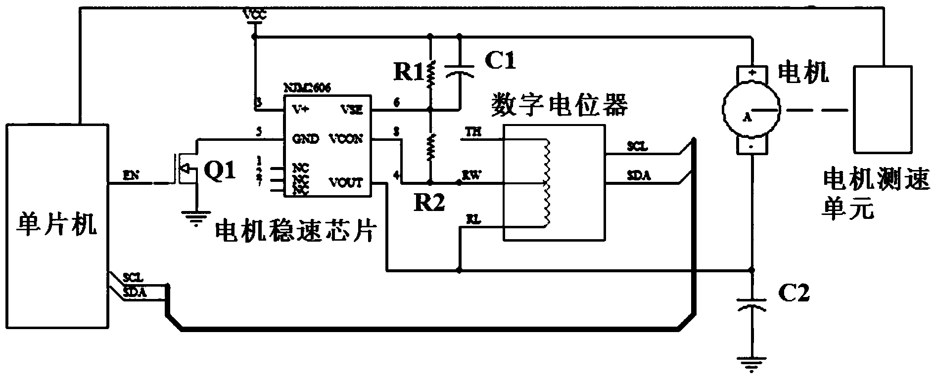
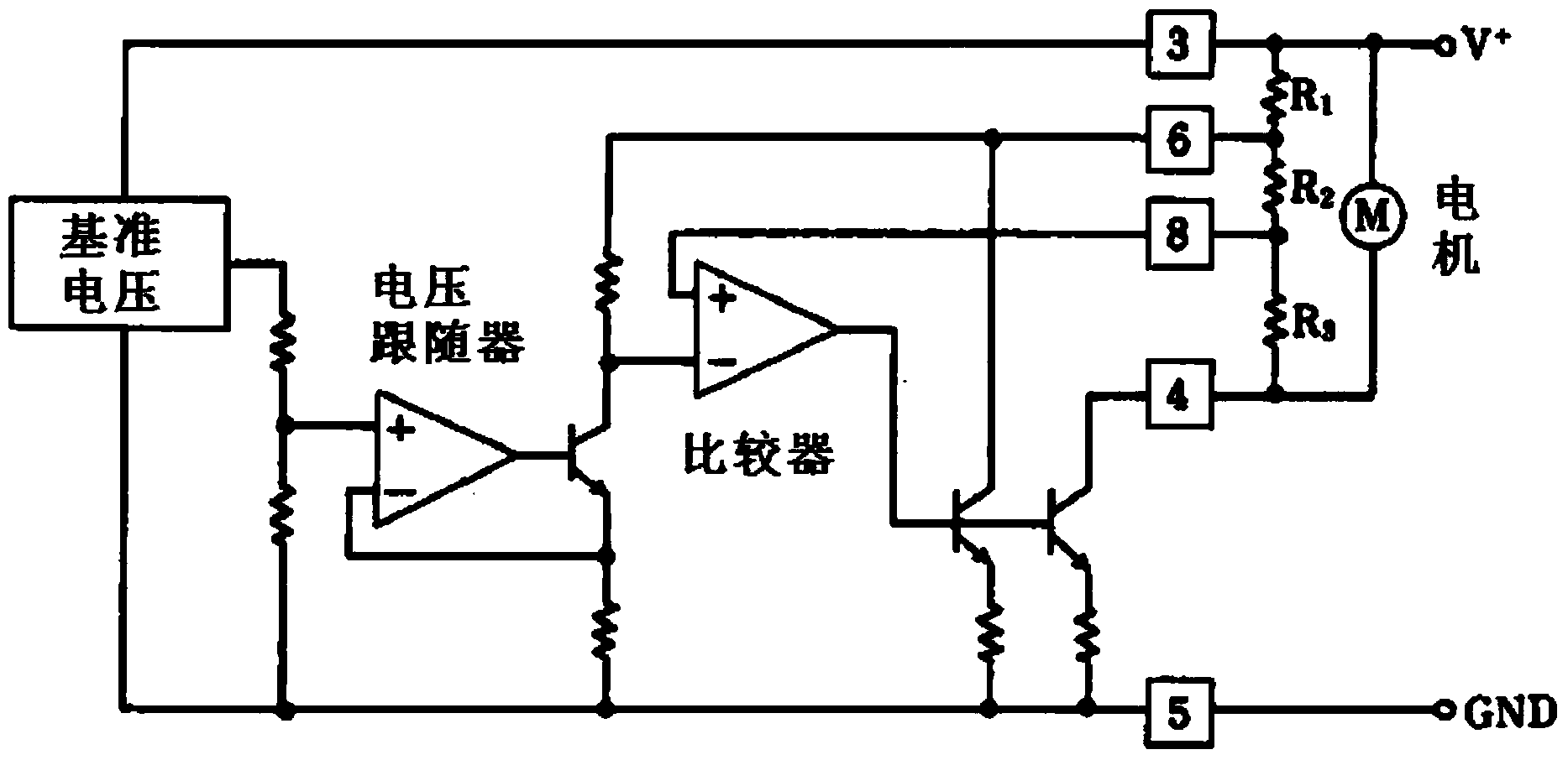
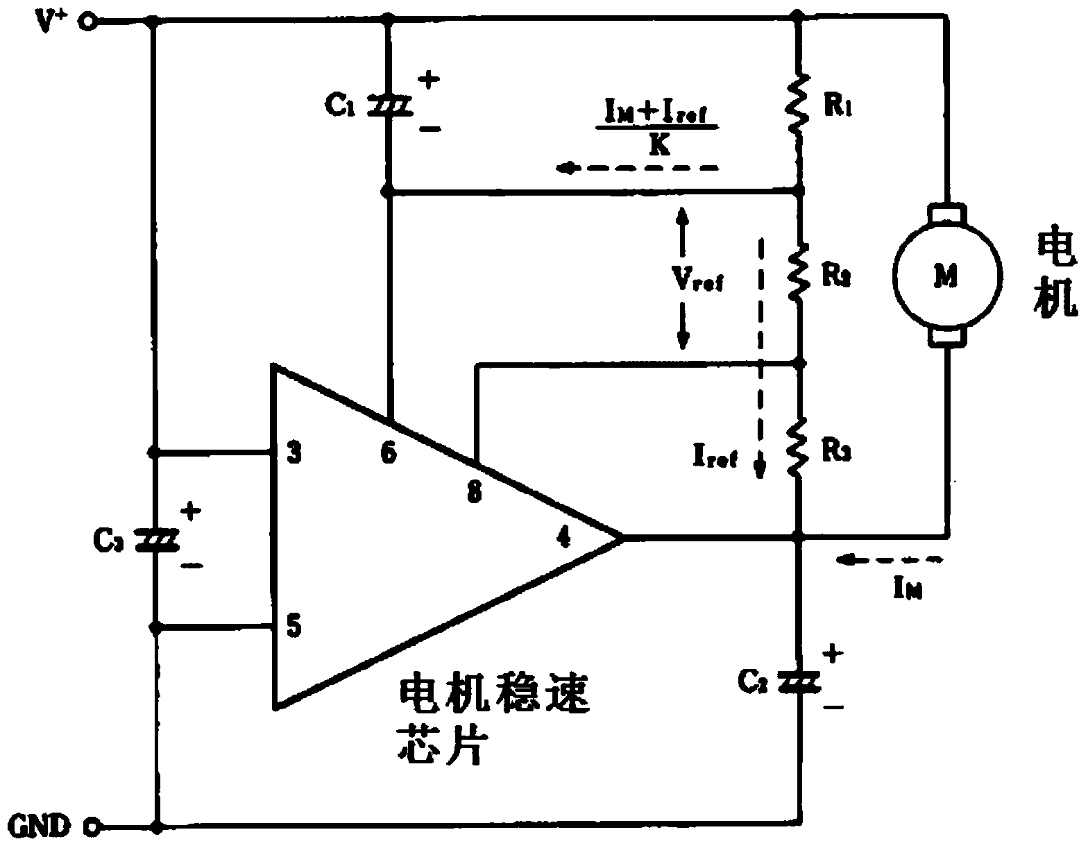
[0028] refer to figure 1 , is a schematic circuit diagram of the motor control circuit in a preferred embodiment of the present invention. In the present invention, the motor control circuit is connected to both ends of the motor of the laser leveling instrument to control the speed of the motor. The motor control circuit includes a motor speed stabilization module and a motor speed regulation module. The motor speed stabilization module adopts the configuration of a single-chip microcomputer and a motor speed stabilization chip. The motor speed stabilization chip is connected to both ends of the motor, using its own properties and functions , to stabilize and adjust the motor speed at a constant speed. The single-chip microcomputer is connected with the motor speed stabilizing chip, and controls the working state of the mo...


PUM


Abstract

The invention provides a motor control circuit for a laser swinger. The motor control circuit is connected to the two ends of a motor and comprises a motor speed regulation module and a motor speed stabilization module. The motor speed stabilization module comprises a single-chip microcomputer and a motor speed stabilization chip. The single-chip microcomputer controls the work state of the motor speed stabilization chip. The motor speed stabilization chip is connected to the two ends of the motor. The motor speed regulation module comprises a resistance value adjustable device. The resistance value adjustable device is connected with the motor speed stabilization chip so as to serve as a load of the motor speed stabilization chip. The rotating speed of the motor can be adjusted by changing the resistance value of the resistance value adjustable device. By the adoption of the technical scheme, adjustment time and stabilization time of the rotating speed of the motor are shorter, occupation of resources of the single-chip microcomputer is greatly reduced, and the use efficiency of the single-chip microcomputer is improved.

Description

technical field [0001] The invention relates to the field of photoelectric equipment control circuits, in particular to a motor control circuit for laser leveling instruments. Background technique [0002] The laser leveling instrument is a device that uses a visible semiconductor laser beam to form a laser surface by horizontal rotation as a horizontal reference plane for large-scale construction. According to the different construction sites, the laser leveling instrument needs to have multi-gear rotation speed regulation, and the speed needs to be stable. The speed regulation technology commonly used in the industry now mainly realizes speed regulation and steady speed through PWM pulse width modulation and software PID parameter adjustment. The process of speed regulation and speed stabilization by the above method has the following defects: [0003] 1. When the motor is controlled at a low speed, the feedback time period of the speed detection becomes longer, resultin...

Claims


Application Information

Patent Timeline
Patent Type & Authority Applications(China)
IPC IPC(8): H02P7/28
CPCH02P7/28
Inventor 张瓯牛青王建勇
Owner CHANGZHOU HUADA KEJIE OPTO ELECTRO INSTR
Learn More