On-line power detection method and on-line power detection device for laser

A power detection and power detector technology, which is applied to lasers, laser parts, phonon exciters, etc., can solve problems such as affecting measurement accuracy, large laser spot, and insufficiently simple layout, so as to achieve accurate measurement results and accurate measurement results. , the effect of saving space

Inactive Publication Date: 2014-12-31
WUHAN LINGYUN PHOTOELECTRONICS SYST
View PDF5 Cites 4 Cited by
  • Summary
  • Abstract
  • Description
  • Claims
  • Application Information

AI Technical Summary

Problems solved by technology

[0004] 1. This measurement method is only applicable to the case where the laser output cavity mirror 1 and the laser total reflection cavity mirror 3 are both flat mirrors. For some special cavity types, the laser total reflection cavity mirror 3 uses a plano-concave mirror, and the leakage from the lens The divergence angle of the emitted laser light increases, which may cause the laser spot to be larger than the target surface of the power detector, and the measurement result can only reflect the local laser power
At the same time, due to the energy distribution of the laser spot, the ratio of the local measurement power to the overall spot power cannot be kept consistent, which will seriously affect the accuracy of power measurement.
[0005] 2. This measurement method cannot be applied to frequency-doubled lasers, because only the fundamental frequency laser can be measured from the laser total reflection cavity mirror 3, and the frequency-doubled laser power cannot be truly measured
[0006] 3. The pump light will enter the power detector 5 through the laser total reflection cavity mirror 3 and the 45° total reflection mirror 4, so that the measurement result is the result of the combined action of the pump light and the leaked laser light, which seriously affects the measurement accuracy
[0007] 4. The 45° total reflection mirror will cause part of the laser leakage during measurement, resulting in a deviation between the measurement result and the laser power leaked from the laser total reflection cavity mirror. Even if this deviation is eliminated by calculating the reflectivity of the 45° total reflection mirror, it will still Inaccurate measurement results due to errors between theoretical and actual values
[0008] 5. There is no reliable positioning device, and the power detector has problems such as inaccurate positioning
[0009] 6. The power detector and the laser are not on the same central axis, but are set at an angle. This arrangement is not concise enough and wastes space

Method used


Image

  • On-line power detection method and on-line power detection device for laser
  • On-line power detection method and on-line power detection device for laser

Examples


Embodiment Construction

[0026] In order to make the objectives, technical solutions and advantages of the present invention clearer, the following further describes the present invention in detail with reference to the accompanying drawings and embodiments. The specific embodiments described here are only used to explain the present invention, but not to limit the present invention. In addition, the technical features involved in the various embodiments of the present invention described below can be combined with each other as long as they do not conflict with each other.

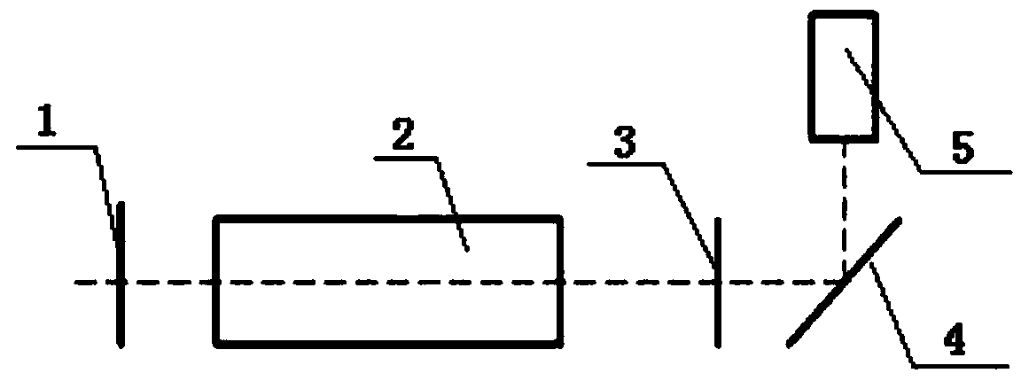
[0027] figure 1 It is a schematic diagram of the structure of traditional power measurement. It is composed of laser output cavity mirror 1, laser crystal 2, laser total reflection cavity mirror 3, 45° total reflection mirror 4, and power detector 5. It places the 45° total reflection mirror 1 behind the laser total reflection cavity mirror 3, and uses the characteristic that the actual reflectivity of the laser total reflection cav...


PUM


Abstract

The invention relates to the technical field of detection of power of xenon lamp-pumped lasers, in particular to an on-line power detection method and an on-line power detection device for a laser. A front laser power detection method is adopted, a power detector is arranged at the front end of a laser output endoscope, and the power of the laser is obtained by detecting the energy of output laser leaked from the back of a 45-degree total reflection mirror between the power detector and the laser output endoscope. The on-line power detection method and the on-line power detection device have the advantages that the detection error is small, the frequency doubled laser can be measured, the on-line power detection method and the on-line power detection device are suitable for the condition that a laser total reflection endoscope is a plano-concave lens, and the normal use of the laser is not influenced in measurement.

Description

Technical field [0001] The invention relates to the technical field of laser power detection, in particular to an online power detection method and power detection device for lasers. Background technique [0002] Xenon-pumped lasers use high-current-density flash lamps to mainly output continuous spectrum, and the output of linear spectrum is less, so a large amount of useless heat will be generated, resulting in extremely serious thermal effects of the laser. The laser pulse power varies with trigger frequency, discharge energy and cooling temperature. There will be big changes due to the difference of the power feedback control system, which usually needs to be equipped with a power feedback control system to measure the laser power and then adjust the flash lamp current in real time. Therefore, how to accurately and reliably measure the real-time power of the pulsed laser is particularly important. [0003] The traditional measurement method of xenon lamp pumped laser is: photod...

Claims


Application Information

Patent Timeline
Patent Type & Authority Applications(China)
IPC IPC(8): G01J1/42H01S3/109
Inventor 林卿王锋
Owner WUHAN LINGYUN PHOTOELECTRONICS SYST
Why Eureka
Try Eureka