IGBT (insulated gate bipolar transistor) dynamic performance test device and operation method of IGBT dynamic performance test device

A test device and dynamic performance technology, applied in the direction of single semiconductor device testing, etc., can solve the problems of not studying the correlation between power cycle intensity and temperature

Inactive Publication Date: 2014-12-31
HEBEI UNIV OF TECH +2
View PDF13 Cites 36 Cited by
  • Summary
  • Abstract
  • Description
  • Claims
  • Application Information

AI Technical Summary

Problems solved by technology

"Testing device for detecting IGBT" (patent application number: CN200910070189) mainly involves measuring the quality of IGBT, and the specific means is to determine its quality by detecting the PWM waveform of the resistor; "A device for detecting IGBT junction temperature and its Method" (patent application number: CN201110038568) mainly involves the detection of IGBT junction temperature, the specific means is to determine the IGBT junction temperature by determining the junction temperature rise of the IGBT and the temperature of the IGBT radiator; "a kind of IGBT temperature detection circuit" ( Patent application number: CN201310230871) mainly involves the monitoring of IGBT temperature. The specific means is to use H-bridge differential i

Method used


Image

  • IGBT (insulated gate bipolar transistor) dynamic performance test device and operation method of IGBT dynamic performance test device
  • IGBT (insulated gate bipolar transistor) dynamic performance test device and operation method of IGBT dynamic performance test device
  • IGBT (insulated gate bipolar transistor) dynamic performance test device and operation method of IGBT dynamic performance test device

Examples


Example Embodiment

[0054] The specific embodiment (detailed explanation in conjunction with accompanying drawing)

Example Embodiment

[0055] Example:

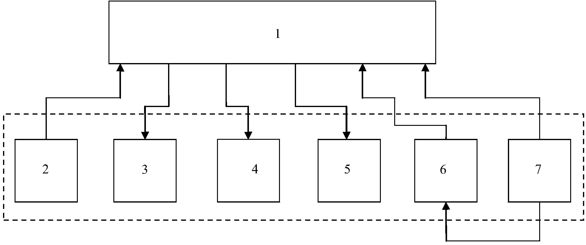
[0056] like figure 1 As shown, the IGBT dynamic performance testing device of the present invention comprises a test current generating circuit 2, a first temperature acquisition and storage system 3, a second temperature acquisition and storage system 4, an oscilloscope 5, an IGBT drive circuit 6, and an IGBT overtemperature protection system 7, wherein, the IGBT over-temperature protection system 7 is connected to the IGBT drive circuit 6; the test current generation circuit 2, the first temperature acquisition and storage system 3, the second temperature acquisition and storage system 4 and the oscilloscope 5 are independent; the IGBT test module 1 during the test They are respectively connected with the test current generation circuit 2, the first temperature acquisition and storage system 3, the second temperature acquisition and storage system 4, the oscilloscope 5, the IGBT drive circuit 6, and the IGBT over-temperature protection system 7.

[0057] T...


PUM

PropertyMeasurementUnit
Thicknessaaaaaaaaaa
Voltage ratingaaaaaaaaaa

Abstract

The invention relates to an IGBT (insulated gate bipolar transistor) dynamic performance test device, which comprises a test current generating circuit, a first temperature collection and storage system, a second temperature collection and storage system, an oscilloscope, an IGBT driving circuit and an IGBT over-temperature protection system, wherein the IGBT over-temperature protection system is connected with the IGBT driving circuit, the test current generating circuit, the first temperature collection and storage system, the second temperature collection and storage system and the oscilloscope are respectively independent, and during testing, an IGBT test module is respectively connected with the test current generating circuit, the first temperature collection and storage system, the second temperature collection and storage system, the oscilloscope, the IGBT driving circuit and the IGBT over-temperature protection system. The IGBT dynamic performance test device has the advantages that the accumulated heat of an internal heating chip and the heat of a copper base board of an IGBT module can be simultaneously and automatically collected, further, the heat resistance parameters of the module can be extracted, and the work frequency of the IGBT module can be adjusted in real time.

Description

technical field [0001] The invention relates to the field of power electronic device testing device and temperature detection, in particular to a test device and operation method of IGBT (insulated gate bipolar transistor) power cycle strength. Background technique [0002] Due to the continuous improvement of semiconductor manufacturing technology, high frequency, high power, and integration are the direction of continuous development of power electronic devices. The power level and power density of IGBT modules are getting higher and higher. High-power devices such as IGBTs are often When electrical devices with electrothermal fatigue are driven by electric energy, their key components will be accompanied by electrothermal effects to cause temperature rise. Constant changes in temperature will produce alternating expansion and contraction forces, which will cause cracks, slack, or even cracks in key parts of the material. Fracture, in the case of high temperature, may also...

Claims


Application Information

Patent Timeline
IPC IPC(8): G01R31/26
Inventor 姚芳黄欢李志刚赵靖英李铮马力岳巍澎李龙朱斯
Owner HEBEI UNIV OF TECH
Why Eureka
Try Eureka