Harmonic optimization and modulation method of multi-level converter
A multi-level inverter, modulation method technology, applied in electrical components, output power conversion devices, AC power input conversion to DC power output and other directions, can solve the problem of limited harmonic elimination and impossible phase shift. Too large and other problems, to achieve the obvious effect of inhibition
- Summary
- Abstract
- Description
- Claims
- Application Information
AI Technical Summary
Problems solved by technology
Method used
Image
Examples
specific Embodiment
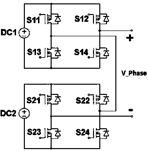
[0031] Specific embodiment: for the H-bridge cascaded three-phase five-level inverter, its single-phase circuit topology is as follows figure 2 As shown, it is formed by cascading two full bridge circuits. DC1 and DC2 are two independent DC power supplies with the same voltage, S11, S12, S21, and S22 are P-channel MOSFETs, and S13, S14, S23, and S24 are N-channel MOSFETs, which ensures that two of the same bridge arm The switch tube is always in the interlock state under the same driving signal, and the output voltage is V_Phase.
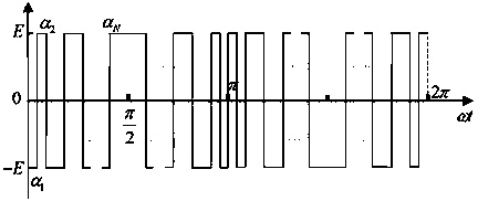
[0032] Step S1: The number of switching angles is N=4, the modulation ratio m=0.8, and the harmonic elimination equations can be obtained from (Formula 3) as follows:
[0033] 2 cos ( α 1 ) - 2 cos ...
PUM
 Abstract
Description
Claims
Application Information
 - R&D
- Intellectual Property
- Life Sciences
- Materials
- Tech Scout
- Unparalleled Data Quality
- Higher Quality Content
- 60% Fewer Hallucinations
Browse by: Latest US Patents, China's latest patents, Technical Efficacy Thesaurus, Application Domain, Technology Topic, Popular Technical Reports.
© 2025 PatSnap. All rights reserved.Legal|Privacy policy|Modern Slavery Act Transparency Statement|Sitemap|About US| Contact US: help@patsnap.com


