Radar system for medical use

A radar system, medical technology, applied in the field of radar system, can solve problems such as prolonged examination, patient discomfort, etc.

Inactive Publication Date: 2015-01-14
SIEMENS AG
View PDF7 Cites 7 Cited by
  • Summary
  • Abstract
  • Description
  • Claims
  • Application Information

AI Technical Summary

Problems solved by technology

However, the placement of the electrodes or the breathing belt required here takes a certain amount

Method used


Image

  • Radar system for medical use
  • Radar system for medical use
  • Radar system for medical use

Examples


Embodiment Construction

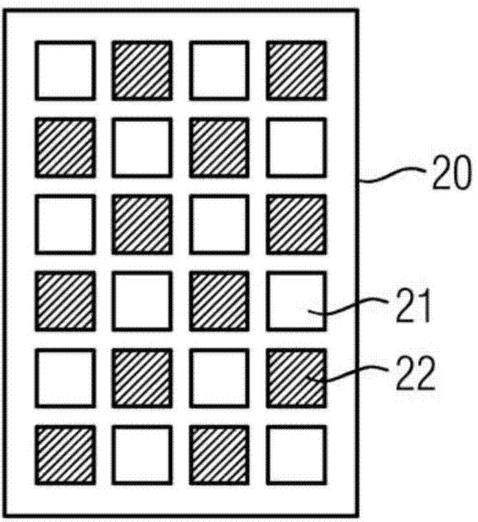
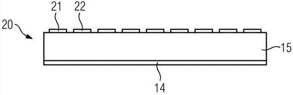
[0028] figure 1 A top view of a radar system according to the invention is shown. The radar system comprises a planar antenna arrangement 20 with an individually controllable transmitting unit 21 for transmitting S radar signals and an individually readable receiving unit 22 for receiving E radar signals. In the example shown here, the transmitting unit 21 is white and the receiving unit 22 is shown shaded. The antennas of the transmitting unit 21 and the receiving unit 22 are respectively constructed in the form of patch antennas. A patch antenna is a planar, generally rectangular antenna whose side length can in particular have the value λ / 2, where λ is the wavelength at which the antenna is used as a resonator.

[0029] The radar system according to the invention can be constructed in such a way that both the transmitting unit 21 and the receiving unit 22 are designed for transmitting S and receiving E radar signals. In other words, in certain embodiments of the inventio...


PUM


Abstract

A radar system, a medical diagnostic or therapeutic device and a method are disclosed for operating a radar system. An embodiment of the radar system includes an antenna arrangement embodied to be flat including individually actuatable transmit units for the transmission of radar signals and individually readable receive units for the receipt of radar signals. The transmit units and the receive units each include at least one antenna. Because the transmit units can be individually actuated and the receive units can be individually read out, the information content which can be obtained even without a strong spatial orientation of the radar beam, is increased. According to an embodiment of the invention, the radar system is designed to assign a radar signal received by a receive unit to the transmit unit which transmitted the radar signal received.

Description

technical field [0001] The invention relates to a radar system, a medical diagnostic or therapeutic device and a method for operating a radar system. Background technique [0002] For a large number of medical examinations and treatments it is advantageous to record movements of the patient, for example heartbeat or breathing movements. Especially in examinations or treatments using imaging modalities such as computed tomography or magnetic resonance tomography, it is important to detect the movement of the patient. Furthermore, the detection of patient movements is also important for medical treatment with radiation therapy devices. The detected motion can be used for motion correction of the acquired image data or for triggering. Typically, athletic data provides information about physiological parameters such as heart rate or respiratory rate. To determine such motion or physiological parameters, it is known, for example, to use an EKG to determine the heart rate and a...

Claims


Application Information

Patent Timeline
IPC IPC(8): A61B5/11A61B5/113
CPCG01S7/02A61B5/113A61B5/055G01S7/03G01S13/48G01S13/583G01S13/88H01Q3/24H01Q9/0407H01Q21/065A61B6/032A61B6/04A61B6/5288A61B6/541A61B6/5217G01R33/56509G01R33/5673A61B5/0507A61B5/02
Inventor T.阿尔曼丁格T.汉尼曼A.亨宁J.佩纳
Owner SIEMENS AG
Why Eureka
Try Eureka